Guide - How to fit a catch can and simplify the PCV system

Guys, just thought I'd give you al a heads up with the atmos venting. Dont do it under the bonnet! I have now become sick of the fumes and whilst on Bill's rollers I could really see how much is coming out of the vent when the car is on full chat.

I have just bought 3 metres of 19mm hose so that I can drop down the engine bay,cable tie the hose along the rear brake lines to vent it near the back of the car.
 
would it not be better just to vent it back into the tip
 
would it not be better just to vent it back into the tip

Lol. I think you've kind of missed the whole point of fitting a catch can in the first place!

When venting back to the TIP you are putting oily vapour into the boost system which reduces octane levels in the fuel and therefore stumps performance.
 
Just the thought of stinky car is putting me off a bit, how protected from the elements will the filter be in its new place
 
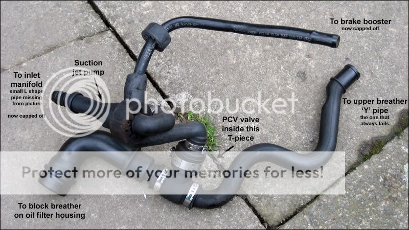
My car has a boost leak and I beleive it is coming from the suction pump, (as its covered in oil) I want to remove the suction pump but dont have the ££ to buy a catch tank, so am just wanting to simplify the PCV system without fitting a catch tank.

My question is what bits will I need to do this? and are there any "how to" guides about?
 
Yeah, you can. I've done this temporarily until I find a proper way to mount the catch can. It's the same as fitting the catch but keep the valve that looks like this and plumb the bottom outlet to the tip and the other end (visible in this photo) to the breather hoses:

018elf.jpg
 
I have all the bits to do this now apart from a non returnable valve for the brake servo pipe, what size will I need and where can I buy one from??

Please can someone point me in the right direction (or even better post a link) :beerchug:
 
I have all the bits to do this now apart from a non returnable valve for the brake servo pipe, what size will I need and where can I buy one from??

Please can someone point me in the right direction (or even better post a link) :beerchug:

Are you kidding me! There can't be any more info in this thread :)

Look on eBay for a "boat non return valve" and you'll find one.
 
Are you kidding me!

so was thinking of fitting one but have a few questions. what does it do? where can i buy one? and how do i fit it?

:p:p
 
Na man not kidding you :)
It does not say anywhere what size non return valve is required, I have searched Ebay and there are many different size valves! I just want to be sure I get one that will fit. Go on link me to one you know you want to :beerchug:
 
Na man not kidding you :)
It does not say anywhere what size non return valve is required, I have searched Ebay and there are many different size valves! I just want to be sure I get one that will fit. Go on link me to one you know you want to :beerchug:

I'll have a look tomorrow mate. I think I used 13mm silicone hose but could only get a 12mm valve so clamped it really tight.
 
Did this today and just reused the one way t-piece as my eBay hadn't turned up yet. It is the most frustrating job I have ever done trying to get it all sorted. Used 15mm outlets with 19mm pipe and just jubileed up tight.
 
what if i just forget the catch can and route the breather from the crank and cam case under the car ??
 
what if i just forget the catch can and route the breather from the crank and cam case under the car ??

You can just forget the can and dump any small amount of oil onto the ground! You will need to block off the hose on the TIP and you'll also need to ensure that the vapour and oil that does come out doesn't cover any of the underneath of the car, or worse, the tyres.
 
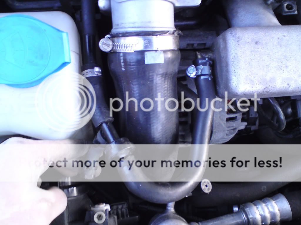
Then I disconnected the brake booster line, leading from the suction pump


IMG_0250.jpg


IMG_0255.jpg


I'm also wanting to cap the brake booster line and just use the 1 vac source for brakes. It works on the AGU and ARZ so no reason it shouldn't work on an AUM right? I used a 1/2" piece of nylon rod and a jubilee clip but have since replaced this section of the brake booster line. Picture of revised piece to be edited in later


IMG_0282.jpg


DSC00886.jpg
[/QUOTE]

Just a quick question I havent got that arrangement in the first picture mines different this is what I have
IMG00351-20111118-1718.jpg

So Do i need to do anything else or have I took off to much and iv replaced the valve with the boat valve so do i not have to block anything apart from the manifold outlet underneath.

Cheers, Chris.
 
No mate all that crap comes off. You just block off the hose under the mani and fit the boat valve on the hose before the left of the mani.

Thanks Neil, all I have to do now is remember where I put the T and 90 bends from Dave cant remember what I have done with the bloomin things grr :banghead:
 
Untitled.png


Sorry for bumping an old thread, Im new here
Was thinking of doing this mod but not sure now and have a few questions.

Would it not be better to take the feed to hockey puck from the top of the catch can - less chance of any oil getting into TIP??

if the oil is getting caught before the TIP, is there much benefit in venting to atmosphere?

Also read a sticky thread from tufty on fitting a Jetex filter. He mentioned fitting a catch can underneath the air box. Are there any advantages in fitting it here instead of fixing it to the bulkhead?

Thanks
 
The picture I did above is for the saikomichi catch can where the outlet is the bottom pipe from the can as it's a baffled can.

I started venting to atmos due to the fact that even with the can, small amounts of oil deposits still made their way into the TIP which can cause a mess and reduced performance.

There's no real benefit of fitting the can in any particular place. It's a tight engine bay so fit it wherever you find easiest to drain it.
 
Just a quick question.. I might have missed this, when you vented to the atmos, what did you do to the piping that connects to the TIP? I noticed the hockey puck was deleted but didn't that vent to the tip?
 
In the diagram at the beginning of the tread it shows the puck sending air to the valve cover during no boost to provide the crankcase with fresh air through the internal passage in the head. When the catch can is set up venting to the tip through the puck is it sending air during no boost through the catch can into the valve cover, and at times possibly the lower breather since there is no longer a pcv valve down there to stop it?

I actually have a 2000 A4 (apr stage3) with no port on the valve cover, Im considering changing to a vc with a port for my catch can set up, and understanding this better will help me decide how i want to go about this. I have been reading alot of conflicting info on the need to have vacuum on the crankcase and provide fresh air to it as well, even though since my vc has no port, I guess audi thought the crank case didn't need fresh air, unless it is somehow going through the lower breather, which I thought only vented the gases.
 
I've got an APY, I was wondering if there's anything drastically different from this guide that I should watch our for when doing this?

I've got oil coming out of dipstick holder (broken :p ) - as I guess there's no where for the pressure to go because my breather pipes have collapsed, so might as well replace the pipes with this. :)

Thanks!
Matt
 
That is a very useful thread Westy, if you don't mind could you please post a picture of your engine bay without the engine cover, after all work is done, just to make sure I understood everything right!

cheers!
 
i have just ordered my Saikou Michi can from america, could anyone tell me if you can get Red oil grade hose as thats what all the other pipes in my engine bay are upto now and all should be when i have tidied the whole engine bay up.

cheers olly
 
i have just ordered my Saikou Michi can from america, could anyone tell me if you can get Red oil grade hose as thats what all the other pipes in my engine bay are upto now and all should be when i have tidied the whole engine bay up.

cheers olly
 
I have an apy nothing different mate( except the piece that comes out of the oil filter housing fell apart, new one 28 quid)
if you vent to the atmosphere, no fresh air to the crank case or valve cover?
 
Managed to order some this afters so when that arrives I will be cracking on with removing half of the crap in the engine bay.
Is there anything else you recommend doing in the engine bay apart from the N249 bypass.
Thanks Olly
 
Right,

Just incase you are all still confused....i have done a revised diagram of Westy's PCV system as he is too lazy to revise it :)


I hope this will make things alot clearer and easier to understand.

ShaunS3PCVSimplification.jpg
 
very useful mate, not doing this whole job myself but am replacing my old pcv. nice to see paint being used lol.
 
Right,

Just incase you are all still confused....i have done a revised diagram of Westy's PCV system as he is too lazy to revise it :)


I hope this will make things alot clearer and easier to understand.

ShaunS3PCVSimplification.jpg


it looks great!

one last question at the "U" shape servo pipe what we should do add there? is that a one way filter?
 
it looks great!

one last question at the "U" shape servo pipe what we should do add there? is that a one way filter?

Not on an S3... the check valve is near the servo behind the heatshielding
20120806_213524.jpg


<tuffty/>
 
This is something i need to do. But what puts me off is the risk of doing it wrong and ending up with either a presurised ( spelt wrong i think) engine or even more leaks from the system.
I looked at AITP for somebody with the bonnet up and the mod done so i could see it first hand... but i didnt manage to see one.