Going to see my bro on Friday so we can do the coil pack conversion and ICM delete (and hopefully play on the dyno and get some "before" figures ready for the freshen up). Any info, tips or advice before we crack on and do it the long way? LoL
I got these https://www.ebay.co.uk/itm/172253542767
And some push in spacers from awesomegti (were about £10 of the top of my head)
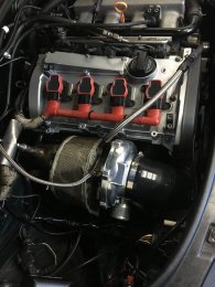
I did solder the connections which I know isn't ideal for automotive applications but wrapped the cabling in a plastic casing as attached, 8 months with no issues so far. Do you have a wiring diagram?
How i did it was lay the repair harness on the rocker cut the unwanted excess wire off leaving enough to play with then using a multimeter i did continuity check to label each wire at the solder end. ie pin 2 coil 1
Then once the repair harness is labelled, strip back the original loom sleeving upto the loom at the rear of the cylinder head then again label your wires up (i labelled them up as to which pin they go to on the 4 pin loom using the wiring diagram as it makes it easy when coming to solder them all up) then cut the sleeving upto the icm (you will have a few extra wires running in this loom that need separating and insulating or conduit as these go to the N75 and MAF) label the wires at the rear of the cylinder head again rather than icm pinout label which pin/coil they go to on the 4 pin loom ie coil 1 pin 4 using the wiring diagram, Then once this is done cut out the old coil part of the loom and then the icm wires you should be left with 5 wires (4 signal wires 1 for each coil and also one ground) the thing to remember is the 4 pin coils have 2 grounds one is the eyelet at the front of the cam cover you will need to make up another for the rear of the cam cover as you will notice one ground is ground twice due to the way its spliced and then the other is soldered to the icm ground wire.
I found it a breeze once all your wires are labelled up for the 4 pin loom.
How it should look when all the wires are labelled up.
The wiring conversion diagram (really help full i printed it off so i had it too hand)
This site uses cookies to help personalise content, tailor your experience and to keep you logged in if you register.
By continuing to use this site, you are consenting to our use of cookies.