I bought the Audi version of a dashcam as I wanted one that integrated with the car nicely and it seemed to have a reasonable specification. I bought it from the offer through the forum and it came with the correct loom for an A3 .
I hope this helps with the UTR specific elements of a dashcam install.
(I have an 2016 A3 8v FL e-tron)
PARTS
- Audi UTR Dual Channel camera kit (contents in PDF) 4G0.063.511.F
- A3 specific wiring harness 4G0.063.511.K
View attachment 165076
(pictures not mine)
TOOLS/FIXINGS
- Trim removal tools
- 8mm,10mm sockets long extension bar
- T25 screwdriver
- tape Measure
- Pliers
- Audi stereo removal keys
- Cloth tape
- Snips
- Pointy Tweezers (or a set of pin removal tools)
- Electrical Tape
- Cable Ties
View attachment 165110
I think the job should take a couple of hours if you choose the easy cable route, there are a couple of points where a second person is very helpful, mostly to align the cameras and the anti glare stickers. It took me a lot longer as I started to follow the Audi instructions to the letter, and realised that this would involve dismantling half the car which i was not prepared to do. I also got stuck trying to repin the fuse box as I could not find any info for how to release one of the pins !
Overall nothing is complicated it may just take a long time to remove some of the trim carefully, it is a moderately difficult job overall.
INSTRUCTIONS
I roughly followed the Audi instructions PDF . Audi specifies that you remove a large amount of trim to route the rear camera cable. I chose an easier route that still avoided all the airbags, interestingly this seems to be the route that was taken by the company that retrofitted my side assist !
Audi Install PDF Link
https://www.dropbox.com/s/szt8zerr2kveqa8/4G0063511K-Front-and-Rear-UTR-Instructions.pdf?dl=0
Route
I choose to run the cable along the front of the headliner, down the A pilar where I picked up the power and ground, down along the door sills up the side of the rear bench and through into the boot where I followed the wiring harness up through the D Pillar then though the cable gland to the boot lid to the rear camera.
The green line in the photos is the route
There was enough length on all the cables to take this route.
View attachment 165083
I have an A3 8v FL e-tron so some things may differ....
I won't go into massive detail in removing all the trim, most of it is self explanatory.
BEWARE OF AIRBAGS ETC DON'T ROUTE CABLES OVER THEM
TRIM REMOVAL
1. Disconnect battery this will vary depending on model mine is in the boot under the floor.
2. Remove front facing camera trim.
View attachment 165082
3. Remove sun visor and sun visor clip
View attachment 165103 View attachment 165114
4. Remove trim from the side of the dash, remove trim from the side of the dash below the A pillar trim.
View attachment 165109
5. Remove A pillar trim behind the airbag logo there is 1 T25 screw. The trim will then pull upwards and away from the dash. Be careful of the speaker cable.
View attachment 165115 View attachment 165095 View attachment 165102
6. Remove the bottom B pillar trim, it unclips at the bottom to get the seat belt trough.
View attachment 165113 View attachment 165101 View attachment 165089
7.Remove the bottom A pillar trim .
View attachment 165106
8.Unclip the bottom of the bench seat, and remove the plastic rivet holding the trim below the seat.
View attachment 165086
9.remove the boot floor
10. My car being an e-tron is very different in the boot as the traction battery is under the rear seats and the petrol tank moves to where the spare wheel would be . I had to remove sound insulation at this point to route the cable up through the D-pillar.
View attachment 165104
11. Pry away but do not remove the D-pillar trim to assist with routing the cable.
12. Pull out the cable gland that goes between the boot and boot lid.
13 Remove the bottom boot lid trim, there are 2 T25 screws behind the emergency triangle.
14. Remove the top boot trim .
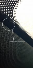
15. Install the anti glare stickers , this is covered in the PDF manual clearly. Be aware when printing the templates that the scale must print out equal to 10cm !!! Be sure to clean the window to help with the adhesion. It helps greatly to have someone help measure the centre and positions and eye up your positioning. Very lightly apply one corner of the sticker and you can readjust it if it is not perfectly straight. When you are happy with the position remove all the air from behind the sticker with a soft cloth.
View attachment 165084 View attachment 165087 View attachment 165112 View attachment 165100
16. Install the front camera base and the rear camera onto the antiglare stickers, again a second person helps to align the cameras.
17.Create the wiring loom. connect both halfs together and wrap with cloth tape breaking off the power and ground at the appropriate points . I cable tied the foam to the first connector .
View attachment 165093
18. Route the cable starting at the front camera tuck it into the headlining and follow the cable route, being careful not run in in front of the airbag, cable tie it too the existing loom, and run it down into the foot well, leave the red and green wires and ground here. run the rear camera cable along the sill securing it to the loom. up and under the bench seat, over the boot floor following the loom up through the D-pillar.
19. The easiest way to get the cable through the cable gland is to tape it to a long blunt thin object i used my universal screwdriver, this can then be forced through the gland easily.
View attachment 165092 View attachment 165090
20. Run the cable along the top edge of the boot lid to the rear camera.
View attachment 165097
(At this point there is a decision to make on wether to use the Audi loom as intended by repining the fusebox, this wasted nearly 3 hrs for me as I could not get the pins out ! Or you can use fuse taps and butcher the Audi loom. I chose to use the nice Audi loom )
...If you use to use fuse taps you can cut the y-chord and attach the fuse tap and route it through to the fusebox... and jump to step 28.
21 Remove the glove box.
21a. First remove the MIB 2 with the stereo keys. Remove all the plugs on the back. The large one hinges from the bottom and most of the smaller ones have a little clip to move so they will release. They are all colour coded and keyed so you don't need to worry about where they go.
21.b Remove the 8x 8mm bolts holding the glovebox in place, you will need a long extension to get the one behind the MIB unit.
View attachment 165080
21.c Remove the glove box, ambient lighting , air bag lockout and glovebox position connectors.
22. Make sure you have disconnected the battery ! There is a red clip at the bottom of the fuse box I believe this isolates it too. Unclip the fuse carrier, there are 3 clips. Pull the fuse box as far forward as it will go being careful of the loom.
23. The Audi PDF suggests that you use position F34 or F35 for the green wire which is the switched live, and position F4 or F10 for the permanent live.
View attachment 165075
I chose to use position F34 and F4 as the were easier to unpin .
24. To unpin F34 or F35 first remove the fuse then purple locking bar. This gave me a lot of trouble at first I could only move it about 1mm, but i couldn't remove the pins. I removed it completely by prying with a screwdriver. This allowed me to remove the pin. Be careful again as I snapped a the tab trying to remove it a second time to take a picture ! I am not sure if this is the correct way to unlock the pins.... Then you will need to insert a thin mental object down both sides of the pin to free it, I used a pair of pointy tweezers whilst pulling the cable from behind.
View attachment 165098
View attachment 165088 View attachment 165108
25. Unpin either F4 or F10. Remove the fuse .This has no locking bar and I just inserted the tweezers and pulled from behind.
26. Assemble the y-chords as the instructions in the PDF with the pins you have just removed. Be careful to insert the pins you have removed into pin 1 on the connector housings and lock them into place by pushing in the grey tab.
View attachment 165094 View attachment 165111
27. Insert the Red and Green wires into the corresponding chambers and replace the purple locking bar. connect the y-chords together as in the PDF.
28. Connect the ground lead to the grounding point down near the door sill. this is a 10mm nut.
View attachment 165099
29. Clip the fuse box back into place Resemble glove box and replace the MIB unit, at this point you should be able to safely reconnect the battery and test that the system is working. My install did not work at this point as I had accidentally disconnected the power loom from the data loom in the roof lining.
The car will light up like a Christmas tree, don't worry take the car for a short test drive to remove the fault codes.
30. Reassemble everything.........
DONT FORGET TO REMOVE THE BLUE FILM ON THE LENSES
THOUGHTS
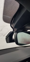
The Audi specified positions have been chosen for a reason, the front camera seems bit lower than it could be but I think that is to stop it from obscuring the auto dimming mirror sensor and from confusing the auto defogger for the windscreen.
It's hard to show from the drivers perspective....
View attachment 165078 View attachment 165079 View attachment 165081
The rear camera is as high as it can be on the window and seems to favour the radar sensor to be central.
View attachment 165077View attachment 165107 View attachment 165096
The quality seems adequate, from my first impressions once i have done some driving I will post some footage. The app like most Audi apps is functional but could be a lot better .
SD Cards
I have bought both a SanDisk Ultra 64Gb card and a 128Gb card and have tested both and seem to have corruption of video I have emailed Audi technical support to find out what the official line is, and will post the response here....
Reference Photos
Fuse Box
View attachment 165118
MIB 2 Unit
View attachment 165085 View attachment 165105 View attachment 165091


")