

Cruise control?
- Thread starter rob v6
- Start date
You are using an out of date browser. It may not display this or other websites correctly.
You should upgrade or use an alternative browser.
You should upgrade or use an alternative browser.
- Joined
- Jan 30, 2008
- Messages
- 18,708
- Reaction score
- 909
- Points
- 113
- Location
- Glenrothes, Fife, Scotland
Afaik the stalks are all interchangable across the range. Theres a part number different for pre and post facelift iirc, but that doesnt mean they arent compatible.

- Joined
- Jan 30, 2008
- Messages
- 18,708
- Reaction score
- 909
- Points
- 113
- Location
- Glenrothes, Fife, Scotland
Ok i looked up the PN's for you.
4D0953513M is the facelift number, and it also suits 1998 and 1999 pre-facelift A4's, and 1994-1999 A8 range.
4D0953513C is the earlier number fitting 1995 to 1997 A4's, however it also is listed as fitting the A8, over the same date range as the other one.
A quick google shows up this:
http://cgi.ebay.de/Audi-A8-D2-Tempo...ItemQQimsxZ20100206?IMSfp=TL100206165004r6704
Which is the same as this:
http://cgi.ebay.de/ws/eBayISAPI.dll?ViewItem&item=230399322736
(the second pic is missing the clamp, but that comes off anyway)
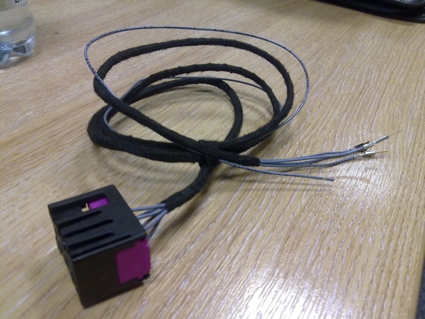
Kufatek harness has just arrived.
I've now got two problems... 1) no colour coding (how the hell are you supposed to know which connector goes where... the wires are bound together in tape, making it nearly impossible to trace them from the connector to their ends!) and 2) there are 6 wires coming out the connector, but I've only got 5 loose ends at the other end of the wiring...
Hmmm...
- Joined
- Jan 30, 2008
- Messages
- 18,708
- Reaction score
- 909
- Points
- 113
- Location
- Glenrothes, Fife, Scotland
Yeah, will do that... then label up the end wires.
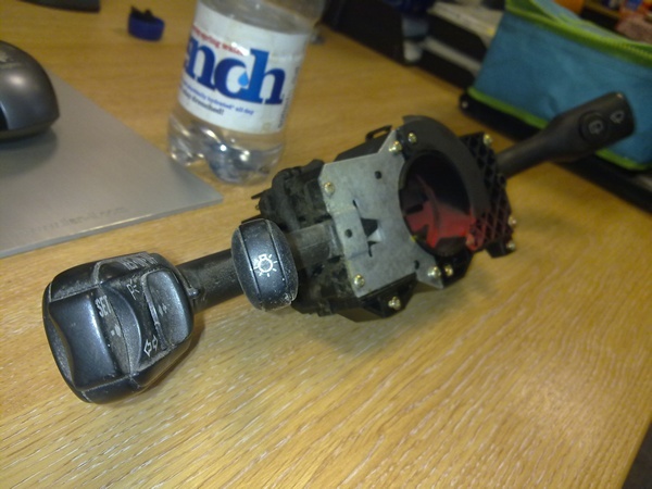
After visiting the scrap yard this lunchtime... here's what I've got...
1) The harness:
2) the stalk(it's a bit grubby... must have been sat outside for ages!)
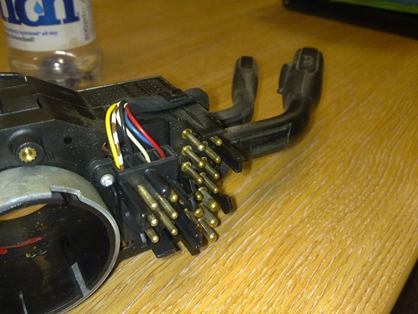
I imagine that one of the wires in the harness is looped into one of the others. The multi-meter will show which one is which, so no worries there.
The other problem I have is that the guide posted here on how to fit the CC to a Passat uses completely different coloured wiring to the wires coming out the back of the CC stalk from the A4 donor.
Aaaaaargh! lol
After visiting the scrap yard this lunchtime... here's what I've got...
1) The harness:
2) the stalk(it's a bit grubby... must have been sat outside for ages!)
I imagine that one of the wires in the harness is looped into one of the others. The multi-meter will show which one is which, so no worries there.
The other problem I have is that the guide posted here on how to fit the CC to a Passat uses completely different coloured wiring to the wires coming out the back of the CC stalk from the A4 donor.
Aaaaaargh! lol
Last edited:
- Joined
- Jan 30, 2008
- Messages
- 18,708
- Reaction score
- 909
- Points
- 113
- Location
- Glenrothes, Fife, Scotland
the plug itself is numbered, use those instead of colors.
I totally screwed up the wiring on mine, because i used the A8 loom with the A4 diagram and went solely on the colors.
I totally screwed up the wiring on mine, because i used the A8 loom with the A4 diagram and went solely on the colors.
Numbered... of course it is!
I'm sure the guide on here is for non-DBW cars though...
I have no problem with everything about fitting this, apart from the wiring (which I guess is the most important part!)
Where can I get an instruction guide/wiring diagram for this?
I'm sure the guide on here is for non-DBW cars though...
I have no problem with everything about fitting this, apart from the wiring (which I guess is the most important part!)
Where can I get an instruction guide/wiring diagram for this?
- Joined
- Jan 30, 2008
- Messages
- 18,708
- Reaction score
- 909
- Points
- 113
- Location
- Glenrothes, Fife, Scotland

Found this...
http://www.vaglinks.com/Docs/Audi/B5/Bentley_Audi_A4_B5_WiringDiagram.pdf
I think 2/6 shows what I need... right?
http://www.vaglinks.com/Docs/Audi/B5/Bentley_Audi_A4_B5_WiringDiagram.pdf
I think 2/6 shows what I need... right?
- Joined
- Jan 30, 2008
- Messages
- 18,708
- Reaction score
- 909
- Points
- 113
- Location
- Glenrothes, Fife, Scotland
Thats not a B5 diagram mate.
ETKA is the vag workshop manuals CD.
I'll dig the cruise diagram out for you in a bit.
ETKA is the vag workshop manuals CD.
I'll dig the cruise diagram out for you in a bit.
Any luck on the ETKA cruise control wiring diagram...?
Incidentally, where can I get hold of a copy of the ETKA myself...? Is it more comprehensive than the VAG CAT I use...?
http://www.vagcat.com/
Incidentally, where can I get hold of a copy of the ETKA myself...? Is it more comprehensive than the VAG CAT I use...?
http://www.vagcat.com/
- Joined
- Jan 30, 2008
- Messages
- 18,708
- Reaction score
- 909
- Points
- 113
- Location
- Glenrothes, Fife, Scotland
geh i'm quoting the wrong names
Vagcat is an online version of ETKA
What i meant to say was ELSAWin, which is the workshop manual.
I'll dig the diagrams out for you this morning, i forgot last night
Vagcat is an online version of ETKA
What i meant to say was ELSAWin, which is the workshop manual.
I'll dig the diagrams out for you this morning, i forgot last night
No worries... lol
Anything will be appreciated! I'm a doofuss when it comes to wiring...
EDIT: I've just ordered myself a copy from the 'Bay of Plenty... but would still appreciate it if you could dig me out a diagram too. :icon_thumright:
Anything will be appreciated! I'm a doofuss when it comes to wiring...
EDIT: I've just ordered myself a copy from the 'Bay of Plenty... but would still appreciate it if you could dig me out a diagram too. :icon_thumright:
Last edited:
- Joined
- Jan 30, 2008
- Messages
- 18,708
- Reaction score
- 909
- Points
- 113
- Location
- Glenrothes, Fife, Scotland

The only pin not showing is {58} which connects to +12v, you can pick this up at the clutch switch or the brake pedal switch, its a black/blue wire.
If you dont have a clutch switch at the moment, you need to add one, i can show you the diagram for that if required.

- Joined
- Jan 30, 2008
- Messages
- 18,708
- Reaction score
- 909
- Points
- 113
- Location
- Glenrothes, Fife, Scotland
It might already be there, but yes, the ecu needs to know you've depressed the clutch when cruise is active, or it'll ram the revs round to the limiter...
Apologies for being annoying, but bear with me.
From that diagram, I've got this in my head...
CC pin No.1 goes to pin No.7 on white ECU connector
CC pin No.2 goes to pin No. 8 on white ECU connector
CC pin No.3 goes to pin No. 9 on white ECU connector
CC pin No.4 is looped to CC pin No. 6
CC pin No.5 goes to clutch switch
CC pin No.6 goes to pin No.10 on white ECU connector
Now... that makes some sense to me now. It was the whole wire colouring (or non-colouring) that was throwing me. If I keep to pin numbers, I think I'll be okay.
THANKS VERY MUCH!
Hang on... you mention [58] being a 12v +ve connection from either the clutch or brake pedal. Does it want to connect to both switches so that it turns off the CC in both circumstances...?
Last edited:

- Joined
- Jan 30, 2008
- Messages
- 18,708
- Reaction score
- 909
- Points
- 113
- Location
- Glenrothes, Fife, Scotland
pin 5 is just 12v power in.
Brake and clutch switches also have a 12v feed to them (with their other side connected back to the ECU), so its just a useful place to take it from.
If you needed to add a clutch switch, it would have 12v to one side of it, and the other side connected to the ecu.
Also, your saying you'll connect these to the "white ECU connector". The white "T15" connector is actually in the plenum, behind the ecu, not on the ECU itself. If there is a connection between that white plug, and the ECU harness, then you can simply attach them there as you describe. If there isnt a connection there, you need to take it directly to the ECU multiplug itself on the appropriate pin numbers.
I've never done this personally, so i dont know whats present and what isnt.
Better for me to get everything physically in place and then get an auto electrician in to wire it in...?
I'm sure they'll appreciate that all the 'hard work' is already done and there's a nice wiring diagram...
I'm sure they'll appreciate that all the 'hard work' is already done and there's a nice wiring diagram...
- Joined
- Jan 30, 2008
- Messages
- 18,708
- Reaction score
- 909
- Points
- 113
- Location
- Glenrothes, Fife, Scotland
lol dont be a wuss. If the white connector has wires in the other side of it, then just plug it in and off you go.

its four wires into the white connector (getting to white connector and working out how to open it is the hard part)
and one wire to the small red wire in another block
that guide is the one i used (it is for dbw) and once you strip everything down it should be clearer
and one wire to the small red wire in another block
that guide is the one i used (it is for dbw) and once you strip everything down it should be clearer
if its dbw ecu already has those inputs and it controls cruise so all your doing is wiring in a switch
unlike cable where your wiring in a control unit
was doner car cable throttle by the way? would love to fit it to my tqs
unlike cable where your wiring in a control unit
was doner car cable throttle by the way? would love to fit it to my tqs
- Joined
- Jan 30, 2008
- Messages
- 18,708
- Reaction score
- 909
- Points
- 113
- Location
- Glenrothes, Fife, Scotland
I dont like the idea of connecting the flying lead to a red wire. That means its live all the time...
Pick up the correct switched live (Black/Blue) at the clutch/brake switches as the diagram shows.
I've never heard of the clutch switch having to be added to DBW cars before, but the diagram does say the clutch switch is only fitted to cars with cruise, so who knows.
Thanks for confirming its all done at the white block, i wasnt sure.