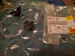
I bought the light from the link below and it came with wiring and instructions in German. I read this thread shortly and going to install during weekend.
http://www.k-electronic-shop.de/AUD...r-beleuchtet---Lichtpaket-Nachruestpaket.html
This is result when translating wiring instructions to English by babelfish. I don't know if these help anybody. At least myself have to still read them through couple of times to understand.
--------8<--------------------------------------
For commissioning as described in point 6.1 can the signal line either on the control unit Connect (thus control possible, lights at the door open, etc.) OR one of the signal lines connect to an arbitrary line of interior lighting which leads to any lit switch.
6.1 integrating you the cables on the network control unit.
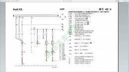
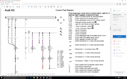
YELLOW line: connector C PIN 3 T73C-> only for models with halogen headlights
Grey line: Plug B T46 B PIN 2-> only for models with Xenon headlights
Led Green: Connector C T73C PIN 62-> only for models with extra lights
INFO: The 3 plugs of the on-board network controller carry the designation "A", "B" and "C".
Depending on the vehicle equipment, connect the cable to the respective connector.
Connection 0V ground at version 6.1
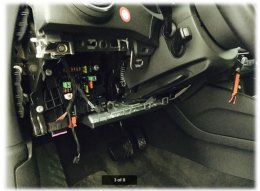
Lay the single wire to the earthing point located at the bottom of the foot area. This is slightly below the lever for the hood opening. To do this, remove the footwell trim by remove the lever and pull off the.
Now screw the ground connection to the existing lines.
6.2 connect the signal cable to the pipe which leads to every button
This is responsible for the interior lighting (the pin assignment varies depending on the button, etc.). Light switch - on this line voltage Also, connect the Brown Earth wire with a Brown ground wire located on a button.
--------8<--------------------------------------
Additonally there are coding instructions, I didn't translate actual coding steps.
7 encoding / activation
The system must be more "free turned on". We recommend to use the latest version of VCDS.
Steuergerät 09 Zentralelektrik verbinden
Steuergerät 09 Codierung Funktion 07 auswählen
Byte 17 Bit 2 von 0 auf 1 setzen
Steuergerät 5F Informationselektronik verbinden
Steuergerät 5F Anpassung Funktion 10 auswählen
Kanal (6) Fahrzeug Menü Bedienung-menu_display_ambient_illumination -> Auf "aktiviert" setzen
Steuergerät 5F Anpassung Funktion 10 auswählen
Kanal (8) Fahrzeug Menü Bedienung-menu_display_ambient_illumination_over_threshold_high -> Auf "aktiviert" setzen
Steuergerät 5F Anpassung Funktion 10 auswählen
Kanal (15) Fahrzeug Funktionsliste BAP-interieur_light_0x08 -> Auf "aktiviert" anpassen
Attached images can also be found from the instructions.