Hi folks, sorry for the delay. I haven't finished my install yet but I thought I'd post what I've done so far.
I'd decided on the firewall install as I think it looks better there than the battery box location, plus there's more room there to drain the tank.
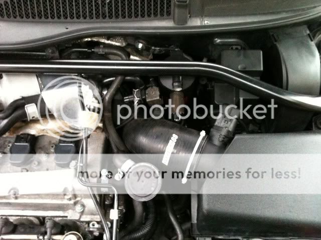
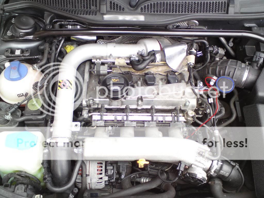
First off I removed the strut bar and the airbox to give myself some room:
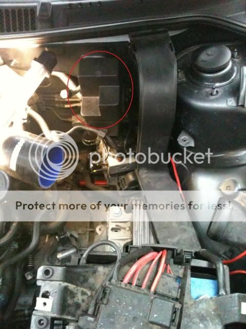
Next, (thanks to a link from Imteyaz) was to get rid of the relay box shown circled in red above by relocating the relay inside it. (This will give more room to drain the tank from the side. It's not essential to remove this, but if left there you will have to drain the can by reaching under the TIP, where there is only a limited space)
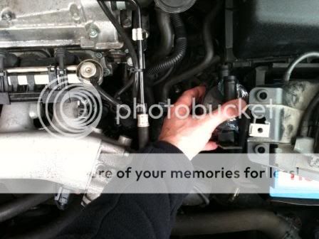
First, remove the plastic cover from the cable run to the right of the box:
Then remove the lid from the relay box:
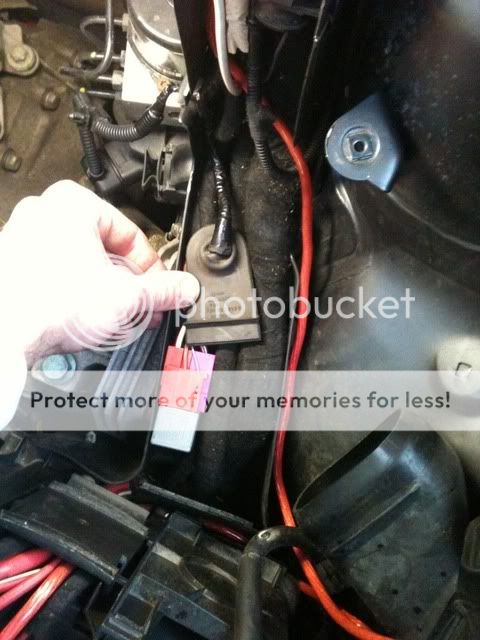
Remove the relay from the box and pull the cable clear:
Now remove the relay box from the bulkhead.
Next, massage the relay and cabling into the cable run area:
Then replace the cover and you are left with this:
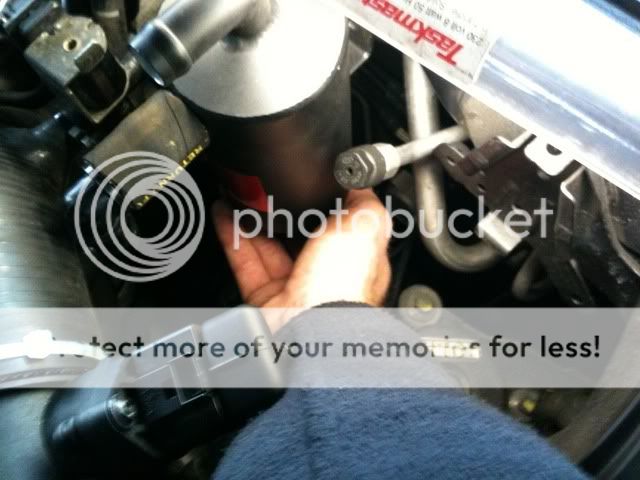
Next was the mounting of the can. The right hand stud shown on the last picture on post #208 was where I wanted to mount it, but I couldn't get a nut to match the thread type. I therefore decided to remove this stud altogether. I did this with a small cutting disc on a dremmel. At a later stage I will rub this down and paint it:
I appreciate not everyone has a dremmel, but there is enough room to get an angle grinder in there aswell if you have one of these. If you have neither, you might be able to get a junior hacksaw in there, but if not all I can suggest is you ask a garage to cut it off for you. They normally have little air driven cutting discs for removing rusted exhaust bolts, so should do the trick nicely.
Now there's two options that can be taken here. The first is to drill a fresh hole in the firewall and use the pollen filter flap to put your hand in and pass a bolt through from the inside. I tried this but my hand was too big to get past the cable runs that are behind there. All I can suggest is that you give it a try yourself and see whether you can get your hand in there.
The second option is to use the left hand stud on the firewall, which is what I did. In order to use it, you have to make some adjustments to the supplied bracket (or make a whole new bracket). First thing is to flatten the supplied bracket:
Then using a vice, make a bend in the bracket which is roughly the same angle as the one on the firewall. Then attach it to the catch can:
I then used one rubber washer and a couple of steel washers to mount the bracket on the left hand stud:
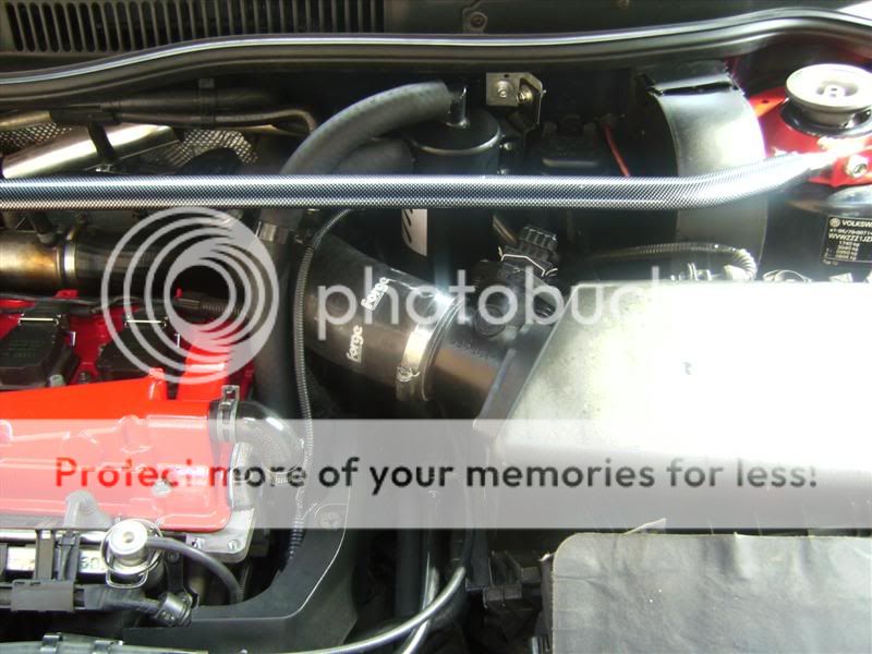
You will have to angle the bracket down slightly so that when you replace the strut bar, it does not catch the top of the can.
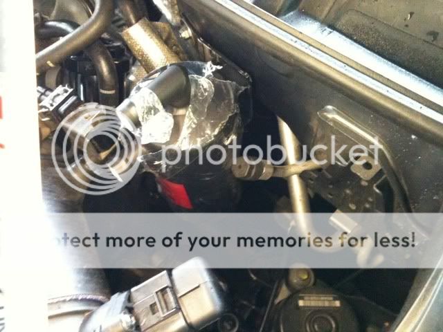
You can see from the following picture that the can is pushing up against the N75 valve, and also the aircon recharge pipe is pressed up against the side of the can aswell:
I got around this by elongating the hole on the bracket and on the can, making the can sit more to the right. I then bent the aircon pipe over so it wasn't rubbing against the side. It does bend quite easily without damaging it, but if you do do this, be it at your own risk.
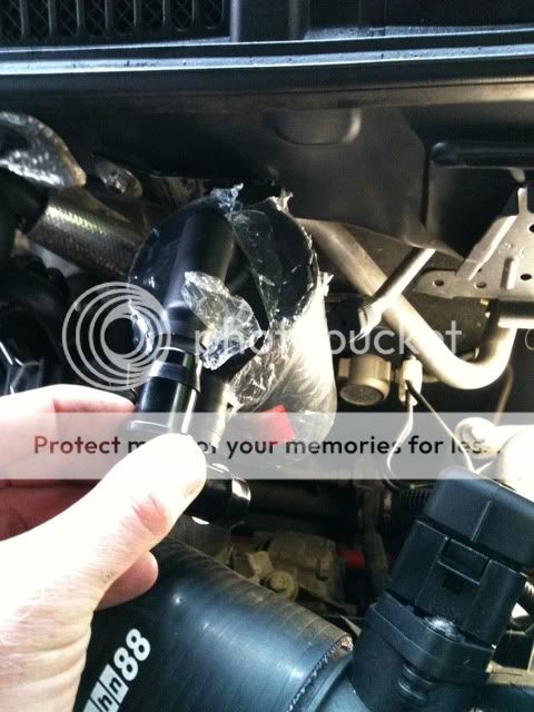
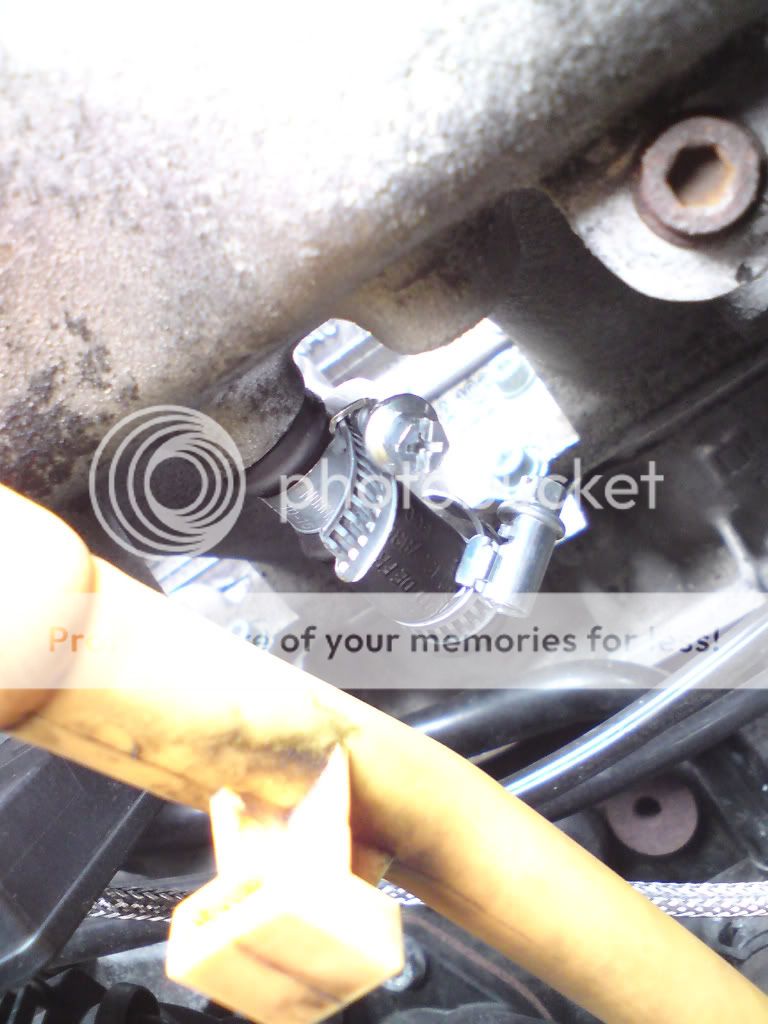
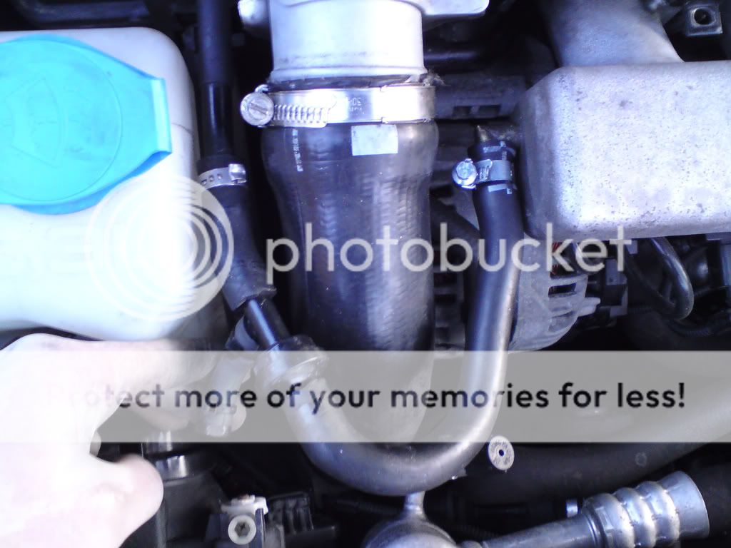
The next job is how to route the hoses to and from the can. You can see from the above photos that the inlet and outlet from the can is quite close to the TIP, close enough that there isn't enough room to bend the hoses down under the TIP. You will therefore need to purchase two 90 degree pipe connectors, like these ones:
http://cgi.ebay.co.uk/ws/eBayISAPI.dll?ViewItem&item=110490634827&ssPageName=STRK:MEWAX:IT
They will point the hoses downwards like the following pictures show:
This is as far as I've got at the moment as I only had one 90 degree pipe connector so I'm still waiting for another one to come in the post.
My plan is to put the PRV (hockey puck valve) directly into the TIP connection and have it pointing upto the outlet of the catch can (bottom connection). The inlet to the catch can will bend underneath the TIP and T-off into the rocker breather and crank breather.
The following picture shows the amount of room available to drain the can with the relay box removed:
The next picture shows the relay box back in place, with very little room for draining:
With the strut bar back in place ( I will be removing the relay box later):
Apologies if some of what I've posted doesn't make sense. I'm writing this whilst really tired, so will check it again tomorrow...
As soon as I get the pipe connector I'll try and get it all fitted asap, then complete the full guide, recapping on the deleted pcv system :icon_thumright:


 Nearside?