Stacey's Belated Yo Yo Build Thread

Just think about load paths mate.

On a cage like yours no tubes should be joining another mid run unless there's a corresponding tube to transfer the load path. The exception to this is in the corners, where it's transfered down the 2 adjacent legs.

If you have front turret supports to go forward from the front legs, I'd suggest they need to be inline with the upper and lower parts of the door bars so the loads are transfered through the whole cage.

One thing to be VERY careful of is elbow clearance too. If you sit very low you may well find it's tight on elbow room. I'd yeah fit a seat and check that before welding anything up.

Done a bit more digging with they're photos they've supplied and although the CAD drawing they supplied shows them meeting at the same point on the A pillar upright the pics of one installed suggests differently which is strange??
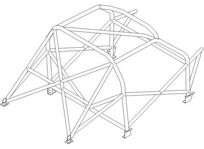


Excuse the poor quality of some as when I opened the cd with the pics on the computer I just took a load of photos on the phone of the screen for reference


Also either I or they have made a monumental **** up and got the pass side door diagonals the wrong way round as the drivers side suggests the longer bar is at the bottom lol


I have tried to work out the rough seating positions but found it quite hard without some kind of subframe and steering wheel etc to gauge from :(

At the moment I think I'll probably trim the bottom tube and fit something like this


As you say if the top front turret support is as near to the bend as possible then should spread the load a bit more evenly along both directions, although due to the lower support would expect it to be directed a bit more up the top section?
 
Iv probably got no good advice for you but when me an a friend put a cage in his track mk2 It was very similar to the porblems your having e.g. we had to cut abit of main a frame to get it to fit. An also door diagonals wernt fitting at all! We thought stickers were wrong too! An noticed the cuts on the poles didnt allow the poles the line up correctly so most of the time we had to modify the cut faces to align properly.

only bit of advise I could give is sello tape or zip tie it together then stick some taks around to hold until its all together as one section could easily push out another section! Blag!

good luck! Still tempting with the idea of caging my s3 at some point so glaD someone else is trying it on here first hah! :)
 
have you tried speaking to custom cages? surely they're the best people to advise how you could do it without compromising the strength of the cage. Even if you just ask them to clarify the door bar positioning as the drawing doesn't match the installed images.
 
Iv probably got no good advice for you but when me an a friend put a cage in his track mk2 It was very similar to the porblems your having e.g. we had to cut abit of main a frame to get it to fit. An also door diagonals wernt fitting at all! We thought stickers were wrong too! An noticed the cuts on the poles didnt allow the poles the line up correctly so most of the time we had to modify the cut faces to align properly.

only bit of advise I could give is sello tape or zip tie it together then stick some taks around to hold until its all together as one section could easily push out another section! Blag!

good luck! Still tempting with the idea of caging my s3 at some point so glaD someone else is trying it on here first hah! :)

Thanks James it does fill me with a bit of confidence that im doing the right thing with a correct kit for the shell had to also be modified

I swear that they were labelled up wrongly before i removed the labels but we'll never know, i cut around 40mm off of the lower diagonal in the end to get it to fit.
It wouldn't be the first mistake that they made though as theres the two diagonals from the main hoop were missing from the kit and inventary/check list although they're clearly on each picture and diagram. I contacted them and after they pulled up the master CAD drawings and documents its missing from the parts list to which they assemble the kits from, they have now sent these two lengths out to which should arrive any day now :)

have you tried speaking to custom cages? surely they're the best people to advise how you could do it without compromising the strength of the cage. Even if you just ask them to clarify the door bar positioning as the drawing doesn't match the installed images.

I should've probably contacted them again but in the end just went with the pics and the labels on the drivers side, as looked at some other MK4 pics to which also appeared to be this way round.
 
  • Like
Reactions: limbo118118
Got some more time on the car today :)

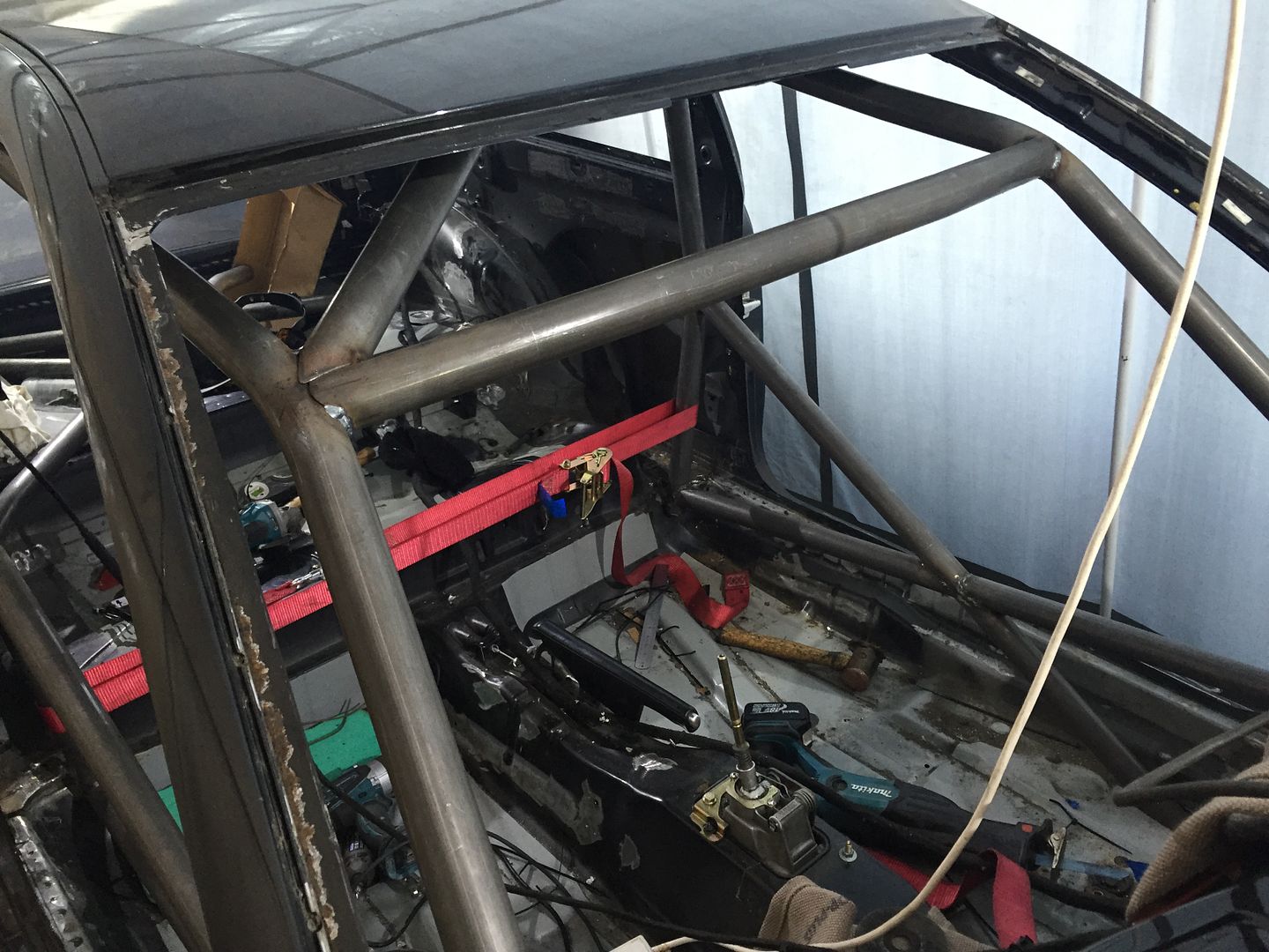
After looking through more pics i decided to go with the bars in this orientation (the way the drivers side labels also said)


I went round welding as much as i could in situ but then went onto cutting the slots in the floor to drop the front end of the cage through


Using two ratchet straps i pulled both sets of legs in with the front uprights dropping off of the feet and into the slots which i had massively under estimated and lengthened in both directions (if was going to do it again i would just cut a section nice and clean with it a lot bigger than what would need also with cuts a bit more strategically placed for rewelding)


Which gave me access to all these


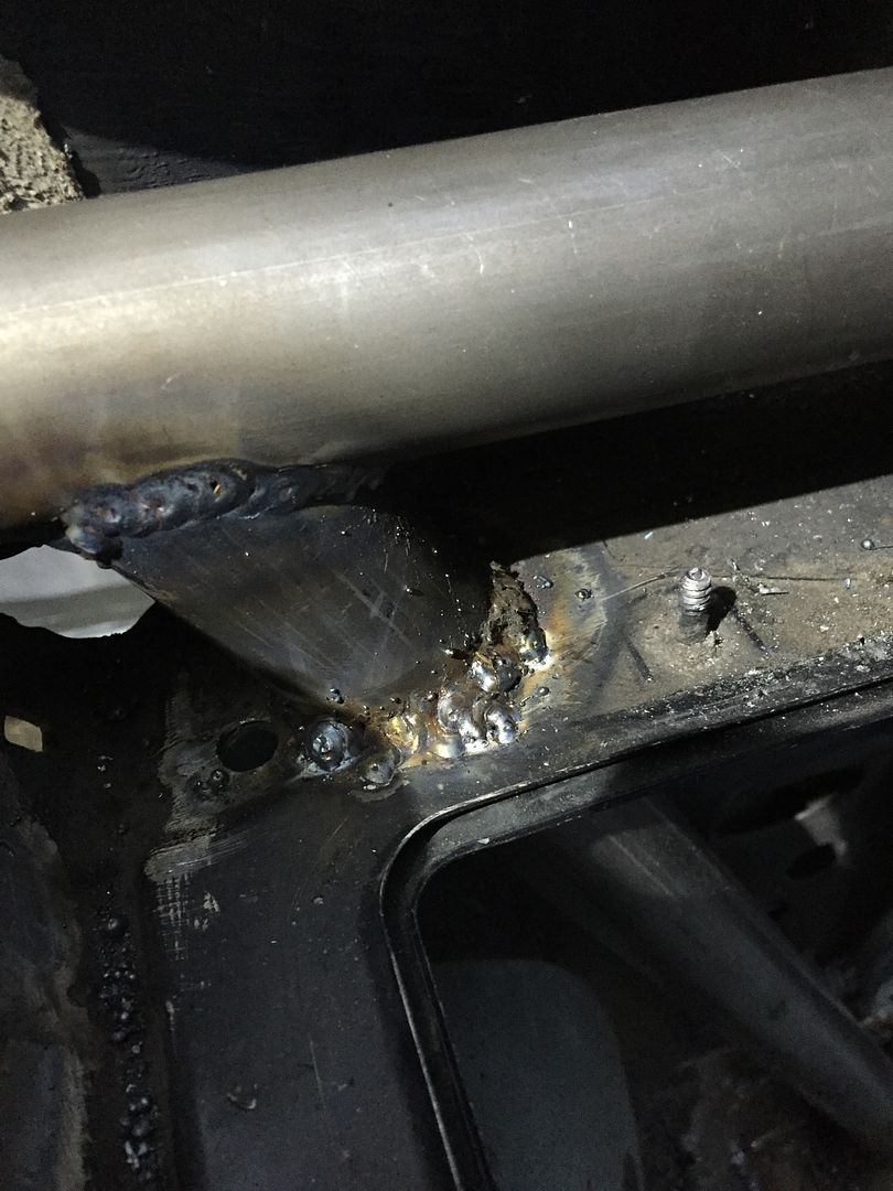
Heres one of the better welds as vertical and upside down welding is an absolute pig! So the nice weld will be hidden in the void and the not so pretty one will be right in the drivers view lol, I'm still glad i'm doing it myself though as enjoy it and its more satisfying :)


Now everything is looking like its correct i revisited the foot plates, started by welding them in permanently followed by cutting up the 3rd side which in hindsight should've cut to fit inside the other piece rather than next to it


Once that was done i set out to lift it back into position and reseat the uprights onto the footplates which due to me making it so tight to the shell involved lots and lots of swearing, sweat, a trolley jack, pry bars, g clamp and a rather large mallet!

I ran a bead around the uprights and that was me done for the day


Hope to get out there again on Thursday for a few hours....thats all for now :)
 
Last edited:
  • Like
Reactions: Sam_, limbo118118, superkarl and 1 other person
Had a late start due to a rather disturbed sleep from the little ones last night, but none the less got some more done

I hadn't profiled and fitted the support bar at the bottom of the main hoop so quickly set out to do this


I used a welding blanket to ensure that the loom doesn't get damaged, as would be a right pig to find if some spatter shorted between 2 cores


Had to just do my best and do a bit of a hit and hope with the welding of the underside of the tube


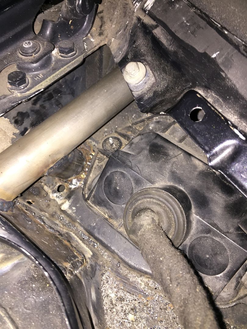
Started on the rear by trying to work out the base mounting points, it appears that they mounted them near these two holes in the boot floor pan but when looking they're an unequal distance from the arches


Although they're unequal distance from the arches the arch profiles are slightly different and measuring from another reference on the body confirmed they're in equal positions, the pic just gives an idea of how i measured it as the level is now where near straight in the pic as only got 2 arms ;)


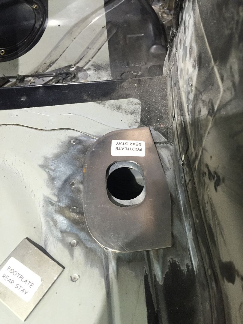
You got 4 plates labelled for the rear stays, i assumed the one with the hole in goes over the top and the little square one to cover the hole


Then once welded in i measured for the center position and marked the upright position


I opened up both of the wholes in the plates as the upright currently wouldn't fit through, this wasn't a precision affair! I just used the dremmel with a carbide burr


Roughly marked out the raised part where the two panels overlap to cut it out


Then went onto the upper and lower rear stay. The upper stay i trimmed 50mm off and 25mm off of the lower to get it to fit into position. I tacked it all into position to then remove them 3 pieces leaving the footplates and weld it in a more comfortable position where can get to all the joins


Once welded, even with a good few heavy tacks it had pulled together during welding so had to use a ratchet strap to pull the lower stay back into position


Quick pic of the not that pretty but more than functional welds


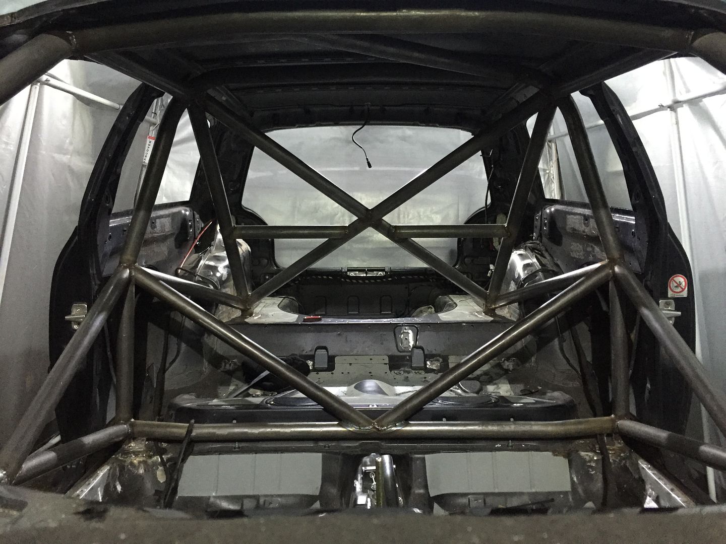
Then finally a few pics of where its at now (i will be trimming the uprights from the rear feet)


Will be a little while until i can get on it again as going back into full swing of work as of tomorrow :(
 
Thanks guys it's much appreciated coming from two people with some fantastic builds like yourselves :)

Really feel like achieved something and getting somewhere now plus have really enjoyed the last month or so getting stuck right in but am worried will fade away a bit for a while now due to work commitments :(
Ultimate goal is to be running for summer at some point but will wait and see....
 
  • Like
Reactions: <tuffty/>
Got a couple of hours on the car here and there over the last week or so

I started by mounting the one piece diagonal at the rear where i wanted it, then measured half way between the two uprights and where this will cross the center of the diagonal, i then used that to align the 2 piece diagonal using a straight edge to make sure its inline and at the same angle. Once they were in i then slung the harness bars in once again using a large steel rule as a straight edge to check they're in line and level. I forgot to take pics of this bit but heres the finished pic of that section


I did whilst i was doing this section have a little fire due to a rag catching light which stupidly id left solvent right next to, got away with it this time but could of gone horribly wrong


A couple of days ago the missing diagonals from the main hoop showed up so stuck them in, that now means apart from the front turret supports the cage is near complete

Hears some pics of how its looking


That then leaves me with the front turrets, i have these two plates supplied to which think will only use half of each one due to the profile of the turret and by their pics they don't wrap the plates around the turrets


For some reason rather than 4 tubes (2 each side) for the turrets i was supplied 6 tubes? Two of which seem to be clearly the diagonals up to the turret (bottom one in the pic), the next one is the top straight to the turret (2nd one up in the pic), then another tube labeled as vertical front support (3rd one up in the pic)


As it appears the profiled top turret straight appears to short so may have to use the other mystery tube or order some more from CC

I then set out by trying to clean the area as best as possible for welding, i had to use a brush attachment on a drill to get in there


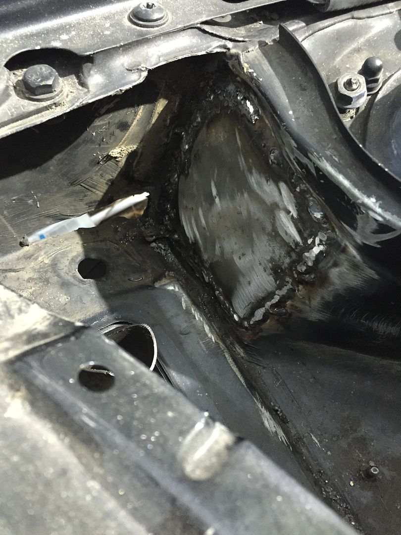
Was an absolute pig to weld as the seam sealant and paint interfered with the weld and very hard to get access to, end result isn't very appealing lol


At this point i had run out of gas, time and didn't have the correct size holesaw i wanted as had forgotten to replace one i had broken a little while ago....DOH so called it a day

I also found that Bill has been marking his territory lol

 
  • Like
Reactions: g60leigh and <tuffty/>
Should be pretty solid when finished especially with some other planned mods I've got in motion ;)

Karl not sure if you mean my back from the ride or something else from the pure excitement..... :D
 
  • Like
Reactions: A3-Lee
Looks incredible!!!!

I hope you've been doing some sneaky Stig training Stacey, when you rock up at a trackday in this people are going to expect big things :racer:

No pressure :laugh:
 
  • Like
Reactions: Dubster5 and A3-Lee
Looks incredible!!!!

I hope you've been doing some sneaky Stig training Stacey, when you rock up at a trackday in this people are going to expect big things :racer:

No pressure :laugh:

Thanks mate, it's a mess at the mo but potential of what it will look like painted and finished is very good :)

I'm going to be so rusty when I get this back as all bar 5 weeks on the GTX it will have been 2 1/2 years since drove it regularly in anger.
I will definately be making the most out of it when it's back for sure even taking it on my 100 mile round commute to work occasionally to which is usually mainly a motorway cruise in the derv but will be all B roads in the S

I'm pretty sure it's going to take me some time to get anywhere near pushing it to the limits on track, to which will probably start with Bedford due to large run off areas ;)
One of my best mates is a predominately a 1/4 mile racer and after dominating his N/A fwd class at USC for best part of 7 years is now building a mk1 1.8t with GT35 so I'm sure will mine will see the strip with his occasionally, although am pleased to say corners are a lot more fun than straight lines :racer:
 
Been having a little look and think over the heating system and suspect that will be able to still squeeze it in but will probably have to loose the actuator for the intake flap that switches between internal and external source


Where the diagonal to the front turrets is going to be passing through the bulkhead it appears it will foul on the actuator, something like this


Does anyone know if can get away with just removing this little bad boy, positioning the flap where I want it and all will still run as norm just with an error code? Bit more of a close up


I've also been doing some thinking on colour of the car to change it to.....
The top favourite at the moment is a light blue, I did suggest the gulf racing colours


But the Mrs shot that one down rather quickly, so something similar but a bit more toned down is currently being considered which I also saw on top gear last night in the test drove M3


Other colours have thought about are different black (maybe Matt), red, white and purple mmmm my mind seems to change daily on other colours but the main one that keeps coming in at the front is the blue with a black interior and roof....opinions and suggestions guys?
 
Last edited:
If you want to simplify the heating could you not see if the heater unit from a lesser model is more suitable?

Basic cars didn't have aircon just normal controls etc... less stuff to go wrong maybe and less electrical stuff to wire up?

<tuffty/>
 
That's a good shout, I'm not sure how much less they have on them? I expect they've all got the valve for internal/external supply?

I've already removed the aircon heat exchanger and blocked it with high density foam


I will be fabricating a metal cap to blank this hole off in the bulkhead
 
Hummm... looking at them there isn't much if any difference between them... the non climate control ones are still electronic flaps from what I can see... there are non AC models I believe but still not sure if that would benefit you at all :(

<tuffty/>
 
You could remove the motor, set the flap to where you want it. Then stick the motor somewhere under the "part dash" so its still connected to the harness.
 
Thanks Paul it was worth a look :)

That's a good idea as should still see the load of the motor think the position switch is external but I'm sure I can frig it ;)
 
Not sure if it just me, but a lot of your pictures in your recent posts are not showing

Stacey
 
  • Like
Reactions: tomjol
If you still want to be able to choose the source of heater air then you could always try rigging a cable up to the flap arm hiding the other end somewhere accessible and inconspicuous.

Something like:


60 inch Locking Choke Cable Twist Lock Universal


Could even lock it into position with that.
 
Not sure if it just me, but a lot of your pictures in your recent posts are not showing

View attachment 50849

I appear to have hit my bandwidth limit with photo bucket to which they close your account and block all links until you upgrade and pay £££ :(

When I first read it yesterday I scanned over it and thought I had gone over my storage limit to which I started a second account under the Mrs email and posted the most recent pics, to then set off and thin out the main account....after deleting a few bits I then realised it was bandwidth usage and not storage....doh

This is the email I recieved from them and thought the tactics were a bit cheeky to be honest


Anyhows on another note that Porsche Riviera blue is sexual


That a good idea Lewis there's no pic coming up for me but I get your drift ;)

I can't imagine I'll need to change it over at all as never seem to in my current cars so may just lock it in position some how?
 
  • Like
Reactions: Scullies
Got an afternoon on the car the other day :)

Started off by tacking the other support plate to the drivers front strut tower in places were it was touching


Followed by using a ball pein hammer to help shape it to the tower and welding more as I shape it


I then used a straight edge to eye up and give me a rough mark to cut through the bulkhead.
I tried to keep it relatively high and as close to the wing as possible so could still use the original pollen filter and connector assembly


It was extremely tight and a very poor angle to get a hole saw in to cut the route through the bulkhead so once again the trusty ratchet strap came out to flex the cage which gave me another 15mm or so extra room


To drill the holes I had to use a 11mm socket on the hex of the hole saw and a 1/4 inch extension which made it rather wobbly but none the less with some careful drilling and brute force it got there


The poles that were marked as designated for this location were to short but luckily there was strangely two others that were also 38mm diameter but about an inch longer in the kit with no purpose so these were profiled for the task


Pic of the 3 tubes for each side although only the 2 longer ones get used


Now that I had the top one at the correct position I used this to eye up and cut the hole for the bottom one


Once both were profiled and to the dimensions I was happy with I set about tacking the bottom one in place whilst the Mrs briefly held it and the bottom one in the desired locations


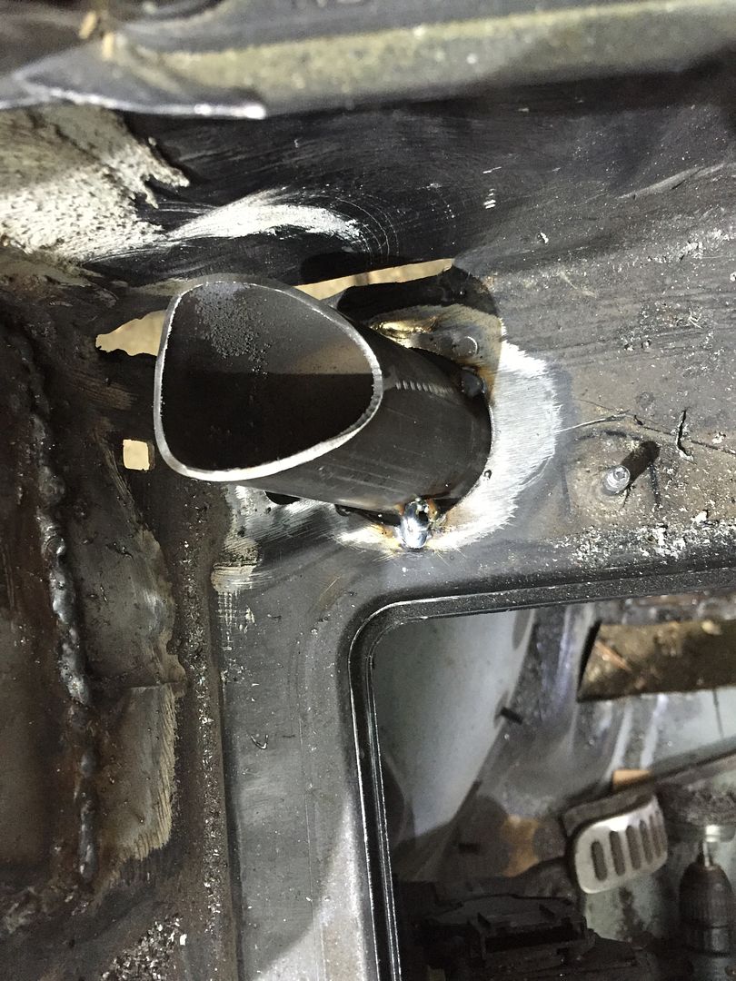
It's not pretty by any means (looks like the pigeons have been at it) and had to keep pulsing it to not get to much heat in and blow it to pieces but I filled the void around the tube to hopefully seal it to the bulkhead (although will also put some kind of sealant over it)

Now that was in position I started to weld the top one in, the join on the 2 tubes I could only get access to weld around 2/3's or so and about 3/4's of where it mates to the turret


Now that was in I done the same on the upper piece were it pass's through the bulkhead and set about filling the gap in. I also forgot to mention but had to cut a couple of slots and bend part of it round to allow me to get the tube in and out


Pigeons also made their way inside the car lol


I also obviously done the same with the other side but won't bore you with the pics, quite chuffed that the loom connector block still fits as well as the pollen filter although can only get one nut on it unless got some ultra thin hands


That now leaves me with only this left of the kit, of which the two tubes are unused :)


And got to finish of a shot of the car (although has vastly looked the same every time)

 
  • Like
Reactions: s3 Hoggy and <tuffty/>
Coming along nicely dude... looking good

<tuffty/>
Thanks mate :)

Anything you can recommend as a sealant to put over the welds etc to guarantee it is water tight protect it from rusting? I've also got to sort out these sodding great holes I cut in the floor :(

 
Been doing some shopping and lots of thinking....

I've purchased this beauty from demon thieves which with a 10% discount code was the cheapest could find it


I've also been doing a fair amount of American shopping to the result my US mailbox is filling up nicely :)

Following a previous phone call with Bill I've decided to make a compartment in the rear over the spare wheel well something like this but to go right to the back of the boot


My current thoughts are to divide it into two with the front half being sealed and airtight, this due to housing the pumps/tanks for fuel and WMI to keep fumes out of the car and to make it safer in event of an accident containing flammable fluids inside. The other side of the partition nearer the bumper was just going to use as a small storage compartment

Am thinking of either a small gauge angle iron frame with panels riveted in to make it or a completely welded box as pictured?

I've also been looking at a replacement battery as my last one expired, I have seen these suggested in a track car thread by mad max iirc, they seem to be very advanced battery tech also with a processor to stop over charge/discharge shutting the battery off but still saves enough charge for a start of the engine for when you attempt to crank it.
To be honest they also seem good value for money as well as being light and small, win/win

https://store.starkpower.com/Starter-Batteries-_c_1.html

Anyone know much about either subjects to through some info in?

Thanks
 
hi stacey thanks for the heads up on prawns thread regarding cages!
i cant believe ive missed your thread?
looks incredible!!!
gonna start reading now!!
god you guys dont muck about!!
 
hi stacey thanks for the heads up on prawns thread regarding cages!
i cant believe ive missed your thread?
looks incredible!!!
gonna start reading now!!
god you guys dont muck about!!

Thanks Daz :)

It looks a right mess at the moment but the finished product should hopefully look and perform well.

I'm looking forward to what you are also doing with yours as have gained some inspiration of the back of it and certainly Mr prawns car with lots of future mods planned due to the crustration ;)

Do love the front bumper cut out on yours it keeps tempting me to attack mine :0
 
Got a little bit done on the car yesterday :)

Welded in the A & B pillar gussets which with a little trimming and bending fitted like so


I did try welding in the V between the B pillar and the plate but wasn't to successful so ended up doing it on the other side through the rear quarter window


This then took me onto a little job in the rear I meant to do a while back, although the kit as CC fit leaves these open, I fancied closing them up


I started by using a bit of CAD to get the rough shape and size of an infill plate


Then once had cut something near the size I tacked a bit of scrap on there to assist the next stage


Once tacked in place I then snapped the scrap piece off and welded round followed by grinding smooth


Car how it stands now


All I can think of that I've got left fabrication wise is modding the dash bar and welding in, repairing the holes in the floor and possibly fabricating the bulkhead compartment in the boot :)
 
  • Like
Reactions: A3-Lee and superkarl
Looking awesome can't wait to get a cage in mine.
 
  • Like
Reactions: StaceyS3


Bet you wish you'd moved your magnet before you started grinding :)
 
  • Like
Reactions: StaceyS3
I'm not even going to ask why you're welding a safe into the boot of the car..... lol

Also
What did you weld the cage with tig 1.6 or 2.5mm arc rods or was it mig wire?
Argon or no argon?
 
Last edited: