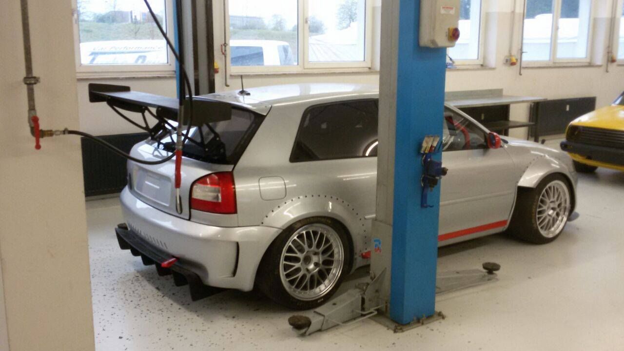
Prawn and BigAls A3 Track Car

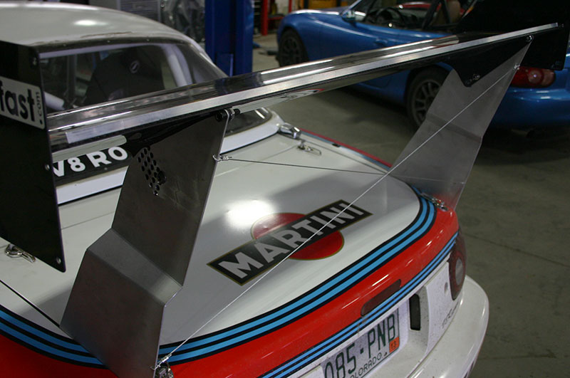
If you can get away without the wire bracing then do, it's pretty horrid for The aero, it's small but it's wake will be far from clean air. To be honest, those brackets are fairly squat compared to what you see functioning fine on saloons with much higher brackets. I'd be inclined to see how it is and only add bracing if necessary.

Really cool to see some more progress. I must find time for a trip over to check out the house and car soon.
 
  • Like
Reactions: Prawn
Thanks mate :)

I'm pretty confid it'll be solid enough myself. But the option is there IF something else is needed. As you say, I hope it isn't though!

The brackets too and bottom will take up to 10mm thickness too, so there's scope to remake in 8 or even 10mm alloy if 6 does prove to be too flexy.

Big thanks to you too for providing the skills to draw it up and the resources to have them made :) without your input it'd have been a much more time consuming job and not to the same standard either :)

You must pop over soon definitely!

I'm currently sat on the Eurostar recovering after an incredible stag weekend (Victoria's brothers) in Antwerp, so don't expect too many evening updates for a few days :laugh:

Journey home includes 4 trains, 2 tubes, and finally an hour long bus ride! Argh.
 
Another option, inverted V shape each side, ie. two mounting points at the bottom of each bracket 2" apart or so? Still a little turbulent, but potentially less so than cross wires perhaps. Would be interesting to see some CFD plots if nothing else :p

Enjoy the trip back...
 
Totally off topic from stag do's.

Are you still rocking them 120,000 mile old bolt down coils?
I know the TFSI Coil conversion is just for show so I've been looking at replacement bolt downs and they range from £12 to £80 each.

Any insight on decent replacements, ours can't be performing their best after 18years and 100,000+ miles, lol
 
glad to hear from big al
not the same in here without you!
bgwv2 is going to be awesome and i have zero doubt you guys will be enjoying finding optimum settings lol

Al you be at curby may 25th?
 
Hi Daz, long see no time. !!! Looking forward to trialing the BGW v 2. We will test, see what happens and take it from there. Don't think it will need any lateral support but if it does we will try something like diagonal wire bracing in .25 mm piano wire. If it is necessary, and I don't think it will be, the turbulence created would be so infinitesimal that it could not be calculated because the wire is so thin and below the clean airflow to the wing. And of course we are not trying to wring the last 1,000 of a second out of it.

As for Curby, alas, I cannot be there. There is a vacancy in the Adriatic for someone to take up a position involving sea, sun and sailing, and once again i can't find anyone willing to take part, so reluctantly I have volunteered. God it's a hard life.
I/ we don't see many track days this year, SAD, but will come back next year with a really good car.

I miss seeing all of the lads at these meeting, but will make up for it next year. :racer:
 
  • Like
Reactions: g60leigh and Prawn
May or may not be of any real use, but fairly interesting either way. DIY Aero thread on an MX5 forum that I stumbled across whilst avoiding doing work this morning. I've only had a flick through a few pages but there's some cool concepts, building techniques and a bit of info dotted about.

http://www.miataturbo.net/race-prep-75/post-your-diy-aero-pics-63769/

For a flick through, stopping when you see any interesting pictures and redaing the surrounding wordy bits there's some potentially useful snippets.

Features such beauties as:

83188-post-your-diy-aero-pics-vlcsnap-2013-07-21-15h35m01s8_zps03905ae6.png

(Page 25)

Also:

77395-post-your-diy-aero-pics-img_2339.jpg


http://www.miataturbo.net/race-prep-75/post-your-diy-aero-pics-63769-post1014713/#post1014713
 
Awesome link Luke!

Just realised there are 42 pages of it! This will give me bedtime reading for weeks!

:racer: Thanks
 
No worries. As much as none of it will be going near my car any time soon (if ever) I find it all pretty interesting to read through.

If I've learned nothing else, it's that despite a couple of people using CFD nearer the end of the thread, the best test for a wing/splitter still seems to be sitting/standing on the part and seeing how it copes :laugh:

Edit:
137742-post-your-diy-aero-pics-downforce.jpg
 
Last edited:
Next one planned for me once the wing is on is some form of side skirts.
Not so much to have any huge effect, but the car is looking pretty aero heavy front and rear now, and in the middle it’s very bare indeed and looks a bit out of proportion.
I was looking at it the other day, and realised that this is largely down to how the sides of the car sweep in from the door line, so by the time you get down to floorpan height it’s ‘waisted’ in by a good 6’’ per side already. This not only looks a bit daft, but it gives a very clear and easy path for air to sweep in under the car, partially undoing the good work of the splitter.
If I could just have an extension downwards, vertically from the bottom of the doors. It wouldn’t even need to go lower than floorpan height to have a huge visual impact, as well as genuine aero merit too.
Idea stolen 100% from RobT and his (former) lovely Ibiza Sprint car:


I believe Rob just used some form of roofing sheets and attached them to the vertical seam under the sills. It was apparently quite effective increasing the efficiency of his splitter by stopping air getting back in under the car, so the splitters gains are felt futher along the underside of the car as I understand it.
My plan would be to mount them slightly further outboard for a greater visual impact.
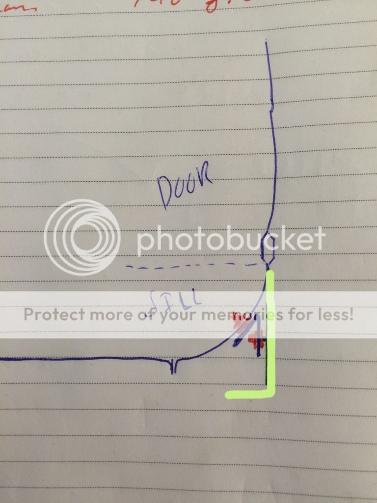
Excusing my awful sketch, this is how I interpret the current stock arrangement:


And this would be my intended plan:


The red indicates a Riv nut in the sill, and again in an inverted V shaped steel bracket. The green then indicates some form of sheet material, most probably using some Mini wheel arch trim along the top edge to give a smart seam / joint to the bodywork.
These could be made and tested at varying depths to see if the gains were felt at all.
Nige at one point ran his just 30mm off the ground and made from rubber strips, and literally let them find their own height be wearing down until they stopped wearing.
In theory, once the brackets are made I could experiement with a few different materials too and see what works best.
 
Concept seems pretty solid - should be relatively straightforward to knock up the skirt itself once you've tracked down some suitable material.

Keen to pop my head round and take a look/lend a hand. Move up to Gosport a week on Monday :)
 
Will be great having you local mate :) Gosport is only 15 mins from me!

Now, gents, tell me if I'm going utterly mad here.....

What about a black fascia board for the side skirt?

5578coba.JPG


It comes in depths of 100, 125, 150, 175 etc etc, so plenty of options for different depths.

Installed something like this:


I know the idea initially sounds a bit bonkers, but I could get a 6m strip of it for under £20, and the return lip 'Should' make them look slightly less DIY.

I don't plan on running them much, if any lower than the lowest point under the car already, so with a small cut out at the front jacking shouldn't be effected, and they shouldn't ever make contact with the ground as they won't be that low down.

Mmmmmmmmmmmmmmmmmm. Something to think about.
 
It's a Dr pepper situation. What's the worst that could happen. You lose £20 ? Go for it.
 
As far as experiments go i think this is a no brainer for you NIck, it might work and it's certainly a lot cheaper and easier then any other upgrades you're looking at!
 
  • Like
Reactions: Prawn
hahahaha
your car must be the only car where most mods come from a builders merchants!!
good for you bud
i reckon it will look sweet mate!!!
and yeh something needs to be done to match the other aero stuff.
 
  • Like
Reactions: Prawn
Al i feel bad for you fella lol
sounds truely aweful!!!
hoping the car isnt gonna get that much better !!!
defo be good to see ya
roll on next year!!! :)
 
Hi Daz, the prospect of two months of S.S.S is truly daunting. I hope it does not scar me for life.

On talking to Nicholas about your car, he tells me it's going to be a bit of a beast. I didn't know you had done all of those mods, well done, look forward to seeing it. It's amazing how many A 3's are now being modified into real beasts. It says a lot about the Audi quality in general. I don't think many people back in the first days of their existence realized how well engineered the engines were. I would guess that the boy's in Ingolstadt would never have thought this revival of the original A 3 would happen, why would they. I went to Ingolstadt a couple of years ago, well worth the visit. Probably more clean than the average UK hospital.

Roll on next year.
 
  • Like
Reactions: daz-20vt
No BBD means more seat time for me at Curby :racer: so it's not all bad :laugh:

Massive thanks to Robin again this evening!

#BGWV2 has taken a decent step forward :)


Getting excited about the final fitment!
 
  • Like
Reactions: StaceyS3 and g60leigh
getting there with some areas Al
not started with others lol
atleast i have this thread to steal ideas from :)
 
  • Like
Reactions: bigal 1
ohhhhh Nick im liking this!!!!
spoiler porn!!!
weekend jobs sorted for you as we all know you cant sit still lol
 
Will the brackets sit a little further from the glass when mounted up, Nick? Looks mighty close there!
 
why are the cut outs not symmetrical?
purely out of interest?
 
Will the brackets sit a little further from the glass when mounted up, Nick? Looks mighty close there!

Yes mate, everyone has asked this :laugh:

The closest anything will get to the screen is about 4mm at the top, where there will be minimal downward loading, and 10mm at the bottom where all the load will be taken :)

With this system the top mount is effectively a pivot point and will resist the drag forces from the wing. Any downward loading (hopefully downforce!) will be seen at the lower mounts at the bottom of the glass.

why are the cut outs not symmetrical?
purely out of interest?

Not sure if I posed this already. But it won't hurt to repeat it:

Due to the angles involved, a small cut out is needed in the 'back leg' like this:


The depth of that notch is around 10mm.

With that rear stay effectively being the main load bearing member, I didn't fancy having it thinner than the others due to the cut out, so I asked Robin to beef it up internally from 30-40mm.

We did think about having the bulge in the outside of the rear leg, but it somehow didn't look right.


I also projected the roof line onto the bracket template I sent to Robin, and he's sweetened that top line so it flows with the roof line and curves up to the wing now instead of a sharp change like my template.

I compared the bracket to my MDF template last night, and given that it took Robin about 30 mins to draw from scratch, I'm amazed that it replicates the template perfectly, even though the template was just a rough free drawn shape. I wish I could use CAD that well!

I'll have a test fit this weekend, and make the final holes for the turn buckle and get everything bolted up. Mum and Dad are coming to stay on Tuesday evening, so I'll have it fitted for when Dad comes here so he can see it and we can go for a drive, then I'll whip it all off and hopefully have it all powdercoated next week ready for final fitment :)
 
  • Like
Reactions: MICHAEL PARKER and Rainbird
no
on your original pics the cut out for the bracket is on an external

the actual brackets the change is on an internal???
so the cuts match in the plans but not in the actual??
 
Glad you're happy with them mate. It was a nice break from drawing bit's of building! I'm really curious to see what they look like bolted up I'm hoping that curve in the top edge works as I'd hoped with it being my only real input to the design of them!

As you know, I'm liking the sideskirt plans and I'm keen to see where they lead. I started having a quick look into materials for a flat under-tray earlier. There's a material we've had samples of at work that I think could be ideal. It's basically a sandwich of high density foam between 2 layers of thin aluminium, could work nicely in theory. I just need to see if it comes in thinner sizes than the samples we have, as well as if it's a) cheap, and b) fairly heat-proof.
 
Id be very interested to hear if it's cheap and heat resistant mate! :laugh:
It sounds ideal in terms of make up. I think something around 6mm thickness would be a good compromise of weight / rigidity.

I'm really glad you did suggest the curved top section, it's going to look much more professional than my basic angular template :)

Looking forward to bolting it up for a first test fit and drive tomorrow :)
 
I saw some hobo aero mods under the rear of a mk4 golf yesterday and thought of you in wickes

188AE5D7-8A50-4932-BF00-FE58EFC88F4D_zpsufg6ctku.jpg
 
That's the same material I was referring to for the diy side skirts lol.
I've used it to make aquarium lids.
 
Hobo looking for sure, and not nicely done, but if that's finished off well near the beam I'd bet it's actually quite effective!

:laugh:

Problem I have is heat. With the exhaust running so hot I wouldn't feel safe with that type of material so close to it.

I don't plan to enclose the tunnel at l, that'll always left open, but I imagine the radiant heat to the floor pan either side of the tunnel after a track session would be enormous, hence the concern.
 
  • Like
Reactions: g60leigh
Agree that it's not a great material for heat. I can test some pieces if needed for you. But for low temp areas it is pretty strong and easy to work with.
 
Some inspiration for you from Austria


Last edited:
  • Like
Reactions: MIGGZ, Vex182, drewman and 9 others

Similar threads

Replies
26
Views
8K
Replies
6
Views
4K
Replies
10
Views
4K
Replies
166
Views
20K
Replies
40
Views
5K