

2.5 V6 Cyliner order
- Thread starter rizla3066
- Start date
You are using an out of date browser. It may not display this or other websites correctly.
You should upgrade or use an alternative browser.
You should upgrade or use an alternative browser.
Can someone enlighten me on the cylinder/injector order thanks?
Attachments
rizla3066
Registered User
How does this tally with vcds?
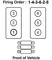
In vcds it says cylinder 2 is the needle point injector but on the diagram it shows cylinder 3 as the one with the needle injector
In vcds it says cylinder 2 is the needle point injector but on the diagram it shows cylinder 3 as the one with the needle injector
That is the cylinder numbering order and AFAIK the injector with the lift needle is on cylinder 3.
It's obvious which one it is as it has the wire connection.
what code are you seeing in VCDS.
http://www.audi-sport.net/xf/threads/how2-2-5-tdi-injector-replacement.116713/
Karl.
It's obvious which one it is as it has the wire connection.
what code are you seeing in VCDS.
http://www.audi-sport.net/xf/threads/how2-2-5-tdi-injector-replacement.116713/
Karl.
rizla3066
Registered User
Thanks for the reply, in vcds i have this
Group 13 - Injection quantity deviation 1
Cylinder 1 = 0.47 mg/str
Cylinder 3 = -0.31 mg/str
Group 14 - Injection quantity deviation 2
Cylinder 4 = -0.16 mg/str
Cylinder 5 = -1.33 mg/str
Cylinder 6 = -0.24 mg/str
That means cylinder 2 is where the wire injector is, but going off that picture it would be the middle cylinder on the left but we know thats not correct as the wire comes from cylinder 3 on the picture
rizla3066
Registered User
Still cant work this out, im trying to get some ideas from elsawin but thats just as confusing.
In the 'Dynamic check of injectors' section its says
– Read measured value block, Display group 13 (cylinders 3 and 1), engine running at idling speed.
l Specification: -1.50 mg/H ... +1.50 mg/H (milligrams per stroke)
– Read measured value block, Display group 14 (cylinders 6, 4, 5), engine running at idling speed.
l Specification: -1.50 mg/H ... +1.50 mg/H (milligrams per stroke)
This tallys with what VCDS says and sugest cylinder 2 is the needle sensor. Going to 'Removing and installing injector with needle lift sender -G80-' sevtion we have this;
– Unplug connector for needle lift sender -G80- (brown connector on bulkhead).
– Slacken the two nuts -arrows- on retainer for injector in No. 3 cylinder.
– Pull out injector together with needle lift sender -G80-.
So this correctly puts the needle sensor on cylinder 3 as referance to the picture. What is right?
I am trying to tally VCDS reading to the correct cylinder, so in VCDS when it says cylinder 3 or 5 i can point to that on the engine.

Injector 3 is the needle lift sensor and all references are compared to cylinder 2 which is the reference point hence no disply in VCDS... I would not worry that much, your readings are ok-ish, cyl.5 is a bit high but still within spec so i would leave it alone...
rizla3066
Registered User
Thanks but thats even more confusing lol? I thought the referance was taken from the needle sensor, cylinder 3 on the pic, and displayed as cylinder 2 in vcds? But you are saying its taken from cylinder 2 on the pic the pne with mo wire? So the reading in vcds for cylinder 3 is infact the needle sensor?
What you are looking at is the fuel injection correction factors applied to each injector. As each injector doesn't flow exactly the same amount of fuel the ECU calculates the time taken for the engine to go from the firing point on one cylinder to the firing point on the next. The time will vary slightly due to the differences in fuel flow of the injectors. This inbalance would lead to rough uneven running, so the ECU corrects the injection duration quantities by small amounts to average out the errors thus you should get a smooth running engine.
This changes dynamically as the engine ages and injectors wear so hopefully the engine will remain smooth. If there is an issue with an injector or cylinder the correction factor would be large and this shows up.
The needle sensor tells the ECU the exact time that injection is occuring. Thus it can make changes to the pump to either advance or ****** the injection point depending on what the map is actually calling for. It's not related to what you are seeing in the measuring blocks.
I am not sure why cylinder 2 reading isn't shown. In a 1.9 PD engine you see all 4 readings and if you add them they should come to around 0.
As you don't have the reading for cylinder 2 I would guesstiate it around +1.5 to balance the other readings you have.
http://www.cnctechnw.com/PDF/BoschDistPump.pdf
Karl.

rizla3066
Registered User
Thanks mate but im still no further. I understand that the 5 cylinders shown are deviations from the main needle sensor.
In VCDS group 15 we have the quantity injected by the needle senseor. (Cylinder 2)
In VCDS group 13 & 14 shows the deviations for the 5 cylinders comapared to the reading in group 15. (Cylinders 1,3,4,5,6)
So going off that Cylinder 2 is the needle sensor?
But Cylinder 2 on the picture is the middle cylinder?
I know the needle sensor is not in the middle cylinder?
I would not worry too much if i were you, it may have something to do with the firing order as that's how the engine's ECU see it- similar to some 4 cylinder fords where programming injectors is a pain in the but- now imagine you had 6 !
Jimbohillbill
Registered User
- Joined
- Mar 8, 2017
- Messages
- 2
- Reaction score
- 0
- Points
- 1
Hi there sorry to bump this thread but this is the closest thread I could find to help try to answer a query.
I have been having ongoing rough idle problems when at optimum temperature also difficult called starts.
The cam belt has been replaced and the timing has been adjusted via a VCDS also DMF has been changed and the EGR valve has been changed to.
I have plugged in the car to the VCDS and tested the injectors which have had the same readings as this thread but different values in that I am missing Cyl 2 readings. My oil level has risen which tells me that the injector seals need replacing and I have ordered some more to go in next week but I need to know with any of my injectors databasing to? Can anyone offer advice or direct me anywhere that might help? here are my readings thank you.
Group 13
Cyl 3 -0.39
Cyl 1. +1.10
Group 14
Cyl 6. +0.55
Cyl 4. +0.31
Cyl 5. 0.00
