Wiring cables to engine compartment

CK87

Registered User
Joined
Apr 2, 2019
Messages
131
Reaction score
12
Points
18
Location
Netherlands
Hello,

1. Currently i’m retrofitting the hold assist option.
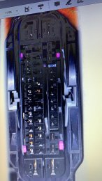
I have to move the wire from the footwell to the engine.
I should remove the battery and there should be a spout that leads to the footwell.
Can somebody verify that it is indeed the spot with the red circle?( see image)

2. Does somebody know where the wire from the electromechanical handbrake leads to? Some kind of module somewhere? Since i have to connect it to pin 5, i was also wondering what the function of pin 5 is. Maybe somebody knows that.
 

Attachments

  • 6D9DD2FA-E588-4A68-9CEA-39F69CA1C1C2.jpeg
    6D9DD2FA-E588-4A68-9CEA-39F69CA1C1C2.jpeg
    670.2 KB · Views: 300
2. Does somebody know where the wire from the electromechanical handbrake leads to? Some kind of module somewhere? Since i have to connect it to pin 5, i was also wondering what the function of pin 5 is. Maybe somebody knows that.

Pin 5 on the handbrake switch is for background illumination.
 
Ah thank you.

Do you have the hold assist retrofitted as well? (Regarding the wiring matter to the engine compartment, just some extra verification)
 
No 8p but I would assume its same place if you know what I mean. I looked at all possible routes this was the only one that worked

Sent from my SM-G960F using Tapatalk

Yes I know what you mean.
That is also the only place I can imagine a cable could get through.
You also agree with me that it's way better to use a push-pull-cable and start from the motor compartment side to the footwell?
If I'm correct, I think I should just insert the cable right under the very thick loom (I think that is some sort of main wiring harness that is currently passing through that hole.
Yeah I removed the glove box. And the battery loom was in place with a grommet i just used a coat hanger to push through then checked to make sure it didnt interfere with anything then attached cable and pulled it through. Did it this way to do it right. Dont rush mate check it a few times do it once.

Sent from my SM-G960F using Tapatalk
 
Ah thank you.

Do you have the hold assist retrofitted as well? (Regarding the wiring matter to the engine compartment, just some extra verification)

Yes. Not sure about your car, but mine is a LHD and automatic, so I used the free hole that is used by the clutch pedal master cylinder in manual cars. It's located at the left side footwell covered by a rubber grommet. You don't need to remove the battery to find it in the engine compartment, but removing it makes things much easier.
 
  • Like
Reactions: leonwilliams
Yes. Not sure about your car, but mine is a LHD and automatic, so I used the free hole that is used by the clutch pedal master cylinder in manual cars. It's located at the left side footwell covered by a rubber grommet. You don't need to remove the battery to find it in the engine compartment, but removing it makes things much easier.

I have LHD too, but manual gear.
The picture that i've attache it just above the footrest-pedal. Can you show my which rubber grommet you mean? any picture?
 
As for the fuse, i will use a piggy back fuseholder.
If im right, the circled ones are suitable fuse holes for the hold assist (i will use 5A fuse)? The reason i want to piggy back this is, that its nearly impossible to get the fuse box out, so i cant reach the rear side. Maybe i do something wrong?
 

Attachments

  • 13C9A871-B9EA-4332-8525-641023A32EC9.jpeg
    13C9A871-B9EA-4332-8525-641023A32EC9.jpeg
    352.7 KB · Views: 204
I managed to connect the fuse.
But when i removed the battery, it seems there is no way to use the hole (see picture).
The existing plus seems to be covered by some rubber and there doesnr seem to be an opening around it. Somebody recognize this?
Do i have to cut the tape a little so I can insert the cable?
 

Attachments

  • 108F6B14-4B1D-4679-85E7-F279ECC1C503.jpeg
    108F6B14-4B1D-4679-85E7-F279ECC1C503.jpeg
    1.4 MB · Views: 201
Ok now the final step.
I just really cant pry the mid part out? This is needed for me to insert the pins right? Ive tried to pry it the circled hatches on both side, but it just wont move... am i doing something wrong? Actually a little bit plastic brok on one side.. damn this is hard

@Rcord can you please help? How did you do it to get the midde part out? Thats needed right?
 

Attachments

  • C5DE496A-CCDD-479D-955D-88D3260BC3E9.jpeg
    C5DE496A-CCDD-479D-955D-88D3260BC3E9.jpeg
    442.4 KB · Views: 226
As for the fuse, i will use a piggy back fuseholder.
If im right, the circled ones are suitable fuse holes for the hold assist (i will use 5A fuse)? The reason i want to piggy back this is, that its nearly impossible to get the fuse box out, so i cant reach the rear side. Maybe i do something wrong?
The fuse positions you circled on the picture are connected to Terminal 30 (permanently powered) while the OEM auto-hold switch is connected to Terminal 15 (switched when ignition is on). It makes sense because you're not supposed to operate the switch when ignition is off. You might use any position in the row of fuses right below the one you've circled but it seems you have all of them occupied. There is another position you could use, SC51, which is the only one in horizontal position, below the two blue 15A fuses at the bottom of the fuse box. In my case, instead of connecting it to a new fuse in the box, I've extended the positive wire a little more and tapped it to a red/green wire connected to position 8 in the connector 17c (red connector) at the coupling station in the left A pillar (it's connected to the SC34, third fuse from left to right in the row of Terminal 15 fuses) if I recall correctly what I did.
 
Ok now the final step.
I just really cant pry the mid part out? This is needed for me to insert the pins right? Ive tried to pry it the circled hatches on both side, but it just wont move... am i doing something wrong? Actually a little bit plastic brok on one side.. damn this is hard

@Rcord can you please help? How did you do it to get the midde part out? Thats needed right?

I did that only once so I don't remember exactly but I'm sure you don't have do pry on those tabs. Did you try the tabs at the upper (as it appears on the picture) ends of the connector? After you open the connector, you have to push on a pink or purple internal plastic bar that holds the terminals in place in order to release them and allow the removal of the placeholders and insertion of the terminals. In case you have no success, maybe someone can help you if you send more pictures.
 
I did that only once so I don't remember exactly but I'm sure you don't have do pry on those tabs. Did you try the tabs at the upper (as it appears on the picture) ends of the connector? After you open the connector, you have to push on a pink or purple internal plastic bar that holds the terminals in place in order to release them and allow the removal of the placeholders and insertion of the terminals. In case you have no success, maybe someone can help you if you send more pictures.

its so frustrating.. like the last step and now getting stucked.... if only you could remember the way you did it :p
 

Attachments

  • 4B0FB353-574D-4B59-97BE-46778FB02777.jpeg
    4B0FB353-574D-4B59-97BE-46778FB02777.jpeg
    1 MB · Views: 231
its so frustrating.. like the last step and now getting stucked.... if only you could remember the way you did it :p
Can you see the round hole at the side of the connector close to your hand? Maybe you can push through it and slide the internal pink/purple bar so you can insert the terminals.
 
Can you see the round hole at the side of the connector close to your hand? Maybe you can push through it and slide the internal pink/purple bar so you can insert the terminals.

if you look through the side, you will see a little piece purple. But we know the right way is different right?
Has it been that long for you? really unfortunate.. since you managed to do it...,
If you think back, was it really difficult ? did you do something special?

I accidentally broke a little pice of the housing, but i guess that should be a problem for the functionality since the grey lever thing will also hold the connector in place.
 

Attachments

  • DE0BB684-1A13-4362-9DB8-CFF4B59DDECF.jpeg
    DE0BB684-1A13-4362-9DB8-CFF4B59DDECF.jpeg
    600.5 KB · Views: 233
if you look through the side, you will see a little piece purple. But we know the right way is different right?
Has it been that long for you? really unfortunate.. since you managed to do it...,
If you think back, was it really difficult ? did you do something special?

I accidentally broke a little pice of the housing, but i guess that should be a problem for the functionality since the grey lever thing will also hold the connector in place.

I remember wondering why do VAG uses so many different connector housings in different circuits so every new connector is a new challenge. That one was difficult and after inserting the terminals I had to assemble the connector twice because in the first attempt I didn't mount it correctly. A few days ago I had to discover how to disconnect the Airbag module connector, which has a secondary lock that has to be moved before prying on the lever lock, before moving the lever.
Did you check the round hole? I think you can insert a thin (but not sharp) tool, like a torx screwdriver and push the purple sliding bar to release the terminals.

you are so right about the different plugs...
btw, this the back side. there is nothing much to slide is it?
 

Attachments

  • B7EC93BB-8F8A-47CD-9327-956F49C6F4AC.jpeg
    B7EC93BB-8F8A-47CD-9327-956F49C6F4AC.jpeg
    314.2 KB · Views: 216
you are so right about the different plugs...
btw, this the back side. there is nothing much to slide is it?

There must be a hole on each side of the connector (circled yellow). You push on one side to move to purple bar to the release position and push on the opposite side to put it back in lock position. Maybe it's not moving because you are pushing the wrong side.

DE0BB684 1A13 4362 9DB8 CFF4B59DDECF
 
OK , and lets assume that i can push it into some unlock position. does that mean the slot are free to be pinned immediately?
 
OK , and lets assume that i can push it into some unlock position. does that mean the slot are free to be pinned immediately?
You will probably find plastic placeholders the same shape of terminals inserted in the slots you are going to use. I think they will be easy to remove after you release the lock.

EDIT: Another thing you have to be aware when inserting the terminals: the slots in this connector are deeper than usual in other connectors so you may have to use a steel pin or another tool to insert the terminals until they reach the end of the slot. Otherwise you may have a faulty contact or will be unable to put the lock back into position.
 
Last edited:
You will probably find plastic placeholders the same shape of terminals inserted in the slots you are going to use. I think they will be easy to remove after you release the lock.

EDIT: Another thing you have to be aware when inserting the terminals: the slots in this connector are deeper than usual in other connectors so you may have to use a steel pin or another tool to insert the terminals until they reach the end of the slot. Otherwise you may have a faulty contact or will be unable to put the lock back into position.

I had to make sure everything would be okay since I broke a little piece of some plastic housing. So I went to a garage and let the mechanic help me unlocking and inserting the pins(and as expected the broken little part of the black housing was no problem).
It turns out you were right, the lock/unlocking mechanism is through the holes in on both sides.

Now the next thing is getting the auto dimming exterior mirros fitted :), I saw on another thread that you've done that as well.
 
  • Like
Reactions: Rcord
It turns out you were right, the lock/unlocking mechanism is through the holes in on both sides.

Now the next thing is getting the auto dimming exterior mirros fitted :), I saw on another thread that you've done that as well.

Good to hear you've got everything sorted out. Regarding the exterior auto-dimming mirrors, prepare to find another different connector (at the door disconnector) to deal with.
 
Good to hear you've got everything sorted out. Regarding the exterior auto-dimming mirrors, prepare to find another different connector (at the door disconnector) to deal with.

OK , i am already preparing by reading the provided instructions. So it's some kind of nasty connector again? maybe if I get stuck again, you can give me some advice again :) appreciating all the effort your put into helping me out with some stuff

Though I was already wondering, Is it really necessary to remove/detach the whole side mirror from my car? While i'm reading the instructions, I was wondering if it's also possible to not unscrew the mirror off. Maybe it's just in case something would fall on the ground when pulling the mirror glass out?
I'll be pleased to help if I can. Maybe it's a good idea to post on the dimming mirror thread, or starting a new one, so anyone interested can find it by the title.
Removing the mirror is surely not necessary if it already has the wiring for the dimming glass included the mirror harness. You can check it by removing the mirror cap and seeing if there is a pair of wires (probably black and black/grey) coming into a connector attached to a slot at the back of the structure that is covered by the cap. It's possible that your driver side mirror already has the wiring and connector if it's a power folding mirror. But it's not usually the case for the passenger side. If there is no wiring in the mirror, you'll have to insert it, so I believe you'll have to remove the mirror in order to do this.

yeah sure, good idea. I'll respons in that other thread
 

Similar threads