Wireless Charging Retrofit

I did - and it works perfectly. I bought the charging pad on eBay and the cable harness and coding dongle from Kufatec. I would imagine that anybody with VCDS could do the coding without the dongle. The Kufatec wiring does not include an aerial wire to the roof aerial, but assumes that you mount an extra aerial on the right side behind the rear bumper.

I did put the amplifier in the back, but haven't had the time to install the extra aerial just yet. I don't imagine that the difference in signal strength is that significant though.
Hi mate,
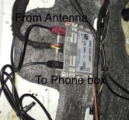
I have installed the phone box with signal amplifier and antenna, wiring done as per Elsa, but I am not sure it is working or not,
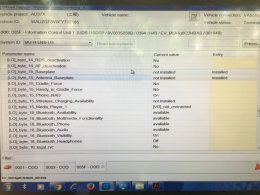
Could you please tell me where we have to change in coding!!!
 
I used the coding dongle from Kufatec, and i would say that it set these bits:

Upload 2020 3 21 15 55 13


If you leave the phone on the charging mat for an hour, the phone will get pretty hot - meaning that it is charging.
 
Last edited:
  • Like
Reactions: mulder85
Hi,
Thanks for the quick reply,
Mine is phone box with out wireless charging.
1) Don’t we need to on Bit 1 —Antenna base plate installed ?
2)Can you tell the Fakra cable connection done is correct
 

Attachments

  • 1B4D6B67-C8AA-48BE-998A-91CBD68BFFD3.jpeg
    1B4D6B67-C8AA-48BE-998A-91CBD68BFFD3.jpeg
    643.3 KB · Views: 470
  • 1F39A66B-C0EA-4240-9547-49B3B436373A.jpeg
    1F39A66B-C0EA-4240-9547-49B3B436373A.jpeg
    332.4 KB · Views: 483
In that case, i would uncheck bits 0 and 5 and check bit 1.
The antenna coupling connections look right.

I don't know how to check if your phone is connected to the external antennas - sorry.
 
In that case, i would uncheck bits 0 and 5 and check bit 1.
The antenna coupling connections look right.

I don't know how to check if your phone is connected to the external antennas - sorry.
Thanks mate,
 
Hi mate,
Please see the attached picture, which shows the opposite of connection,Black connector is connected to Antenna ,
Confused now,
As per kufatech,Could you please tell me black connector goes to phone box and claret violet goes to External Antenna, is it correct ?
 

Attachments

  • 4B385F50-ECE8-4B87-9E19-C04428C689AD.jpeg
    4B385F50-ECE8-4B87-9E19-C04428C689AD.jpeg
    244.9 KB · Views: 469
I did - and it works perfectly. I bought the charging pad on eBay and the cable harness and coding dongle from Kufatec. I would imagine that anybody with VCDS could do the coding without the dongle. The Kufatec wiring does not include an aerial wire to the roof aerial, but assumes that you mount an extra aerial on the right side behind the rear bumper.

I did put the amplifier in the back, but haven't had the time to install the extra aerial just yet. I don't imagine that the difference in signal strength is that significant though.

If I wanted to install it as "phone box Light", meaning without any wiring to aerial, what are the minimum steps in terms of wiring, to ensure the MMI sees it as original equipment?
 
Anybody wanting a genuine wireless cradle/charging pad, I have one for sale. (without cables)

It’s on eBay but let me know and I can give you the details.
 
If I wanted to install it as "phone box Light", meaning without any wiring to aerial, what are the minimum steps in terms of wiring, to ensure the MMI sees it as original equipment?
I would make a single wiring harness.

The black 6 pin connector to the charging pad is called T6bt

Pin 1 goes to fuse SC2 in the left side of the dash (at least on a LHD car) Or you could just take this on the navigation unit
Pin 2 goes to pin 5 in the gray connector T12n in the Quadlock to the navigation unit
Pin 3 goes to pin 11 in the gray connector T12n in the Quadlock to the navigation unit
Pin 4 is ground

That should do it.....
 
Last edited:
  • Like
Reactions: mulder85
Thanks a lot, that's really helpful. I am really a n00b, so I would need to find the courage to do such electrics work on the car. Which one of those 4 is power?How does the qi get the necessary power?

I have seen some cheap copies on ali but it looks like they simply hijack the cigarette lighter for independent power and no other cables are involved? I suppose those would have no communication with the MMI whatsoever (for charging/forgetting notifications)?

I would make a single wiring harness.

The black 6 pin connector to the charging pad is called T6bt

Pin 1 goes to fuse SC2 in the left side of the dash (at least on a LHD car) Or you could just take this on the navigation unit
Pin 2 goes to pin 5 in the gray connector T12n in the Quadlock to the navigation unit
Pin 3 goes to pin 11 in the gray connector T12n in the Quadlock to the navigation unit
Pin 4 is ground

That should do it.....
 
Hey @strandgaard , sorry to bug you with my noob questions. I have some trouble finding the t6bt connector on the internet. All my searches bring nothing back. Do you happen to know a good link from where to buy it? Also, what kind of wire is advised for the harness? Specific gauge, etch?


Pin 1 is permanent 12V and 4 is ground.
 
No problem.
But i am not much help this time.
I bought my wiring loom from Kufatec in Germany, and the connector is part of that loom. The wires are 0,35 square mm's - don't know how much that is in gauge.
See your local Audi dealer and have them look it up in the spare parts catalogue.
 
Thanks a lot, you are awesome! I think based on all the valuable info you have shared, I will collect all the electrics/parts required from ebay/ali/whatever and have a go at it myself, as the local car electricians really hesitate to tell me if this is doable(doubt they have ever done it). Since I am interested in the "phonebox light" implementation with just the 4 wires for charging/notification, I think it would be a shame paying Kufatec 110 euros for the wiring loom. Although I assume the instructions manual came in very handy....?

One last thing, did you use a "piggyback" fuse cable and added it to the phone fuse input(SC2)?


I just had a second look.

The connector is 4B0971978B and the corresponding pins (2 pins with with 0,5 m wire in between) are numbered 000979009E

Connector - https://www.aliexpress.com/item/4000160922800.html
 
I added it to the correct fuse position using a Junior Power Timer pin.
 
  • Like
Reactions: mulder85
That's great. I thought that specific position was not empty, that's why I asked about the piggyback. Doesn't the smartphone interface use that plug? It says "telephone".
I added it to the correct fuse position using a Junior Power Timer pin.
 
SC2 can supply different contri
ollers beside "J1146 Charging unit 1 for mobile devices" - could be J676 chip card reader, R215 external multimedia unit, R126 Telephone bracket. If you have either of these, it will be occupied. I would solder the wire to the fused wire on the back of the fuse holder.

R199 - Connection for external audio sources (Smartphone interface) is SC5

But they are all fixed 12V so you can use any vacant position.
 
  • Like
Reactions: mulder85
Perfect. Thanks again. I will open the box and act according to whether it is occupied or not. Wouldn't it be better to use a piggyback so that an actual fuse can be connected for a proper circuit-breaker?That's if it is possible to pass the cable to the front(facing) side of the fuse box....

SC2 can supply different contri
ollers beside "J1146 Charging unit 1 for mobile devices" - could be J676 chip card reader, R215 external multimedia unit, R126 Telephone bracket. If you have either of these, it will be occupied. I would solder the wire to the fused wire on the back of the fuse holder.

R199 - Connection for external audio sources (Smartphone interface) is SC5

But they are all fixed 12V so you can use any vacant position.
 
Hey @strandgaard , is there by chance any "official" document where this specific wiring you mentioned is shown? I just want to make sure I have the correct information, as I have now collected all the materials and planning to go ahead with it soon. Thanks.

I would make a single wiring harness.

The black 6 pin connector to the charging pad is called T6bt

Pin 1 goes to fuse SC2 in the left side of the dash (at least on a LHD car) Or you could just take this on the navigation unit
Pin 2 goes to pin 5 in the gray connector T12n in the Quadlock to the navigation unit
Pin 3 goes to pin 11 in the gray connector T12n in the Quadlock to the navigation unit
Pin 4 is ground

That should do it.....
 
There is an official wiring diagram for sale (7 euro) at erwin.audi.com

And when i checked, i found a small error in my previous description. It should be:

From the black 6 pin connector

Pin 1 (+12V) goes to fuse SC2 in the left side of the dash (at least on a LHD car) Or you could just take this on the navigation unit
Pin 2 (Can - L) goes to pin 7 in the gray connector T12n in the Quadlock to the navigation unit
Pin 3 (Can - H) goes to pin 1 in the gray connector T12n in the Quadlock to the navigation unit
Pin 4 is ground
 
Thanks a lot for spending the time to go have a second look at it. I really appreciate the updated information.
Considering that the quadlocks are notorious for having very short leash/give, do you have any tips for getting enough space to work on the quadlock?

There is an official wiring diagram for sale (7 euro) at erwin.audi.com

And when i checked, i found a small error in my previous description. It should be:

From the black 6 pin connector

Pin 1 (+12V) goes to fuse SC2 in the left side of the dash (at least on a LHD car) Or you could just take this on the navigation unit
Pin 2 (Can - L) goes to pin 7 in the gray connector T12n in the Quadlock to the navigation unit
Pin 3 (Can - H) goes to pin 1 in the gray connector T12n in the Quadlock to the navigation unit
Pin 4 is ground
 
You need to remove the glove compartment and navi unit. That gives you plenty of give.
 
  • Like
Reactions: mulder85
@strandgard I tried installing it only to find out that pins 1 & 7 on the T12n connector are already utilized. Do we know what else could be utlizing those and what can be done?
 
Send me a PM and let us continue there.
Unfortunately I am not seeing a link for PMing you on your profile page. Please feel free to do so if you can see it on mine
Is there a picture of the T12n pin numbers? I just want to make sure I've got the correct ones. But in any case, 1 &7 should be on a edge side and on mine both edges are filled with pins.
Could it be that because I already have the smartphone interface which charges the phone, those pins go there and take up the spot?
 
I just PM'ed you. And it might actually be 5 and 11 as originally stated
 
  • Like
Reactions: mulder85
I am looking for help too.

I just need part numbers and advice

I have

8w0035502c​

and
8w0864981

but looking at Kufatec listing there is also cables we need, an amplifier and maybe even a different aerial?

Any list of full part numbers would be great. so i can find them for as cheap as possible then locate someone who can just charge labour for fitting.
managed to get hold of the actual wireless charging box completely.
Will now just purchase separate wiring kit from Kufatec for 100 euros.

Any one local to Dorset or London who is able to fit this?

Most places are supply and fit unfortunately.

Also, if its on the wireless charging pad and amplifying signal, can I also use apple carplay via the wire at the same time?
Yes - you can use wireless charging and carplay at the same time - although I would imagine, that the phone charges over the cable connection instead.
 
My retrofit started working out of the blue 6 months later. I have no explanation, it just did, without me touching anything. Probably the fact that I chose to make my own wiring harness and buy used original chargers(instead of going for the brand new OE Kufatec kit), had to play a role on this random experience. What is certain is that the instructions for wiring and coding available to the public, are 100% correct.