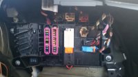
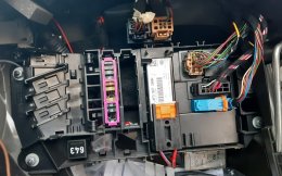
I think this is the control module for the rear light would i be correct ?. Would anyone have a wiring diagram for this as i am at a loss with what to connect up . Any help would be great.
#NumberDescriptionQty.
list of uses; control unit
1control unit for access and; start authorisation; see illustration:; 909-00
2control unit for tyre pressure; control; see illustration:; 907-50
3engine control unit; see illustration:; 906-00; petr. engine
3engine control unit; see illustration:; 906-05; diesel eng.
4control unit for automatic; headlight range control; see illustration:; 941-25
5onboard supply control unit; see illustration:; control unit 2; 907-00
7cd changers; see illustration:; 035-38
7connection for external; audio sources; see illustration:; 035-38
7chip card reader for road; toll system; see illustration:; 035-57
8interface box with software; see illustration:; 'MMI'; 919-10
9control unit for special veh.; see illustration:; 907-20
10display and control unit; for multimedia interface 'mmi'; see illustration:; 919-00
10sender and receiver unit; for road toll system; see illustration:; 035-57
11door control unit; see illustration:; right front; 959-10
12control unit for movement; sensor; see illustration:; 951-40
13control unit for memory seat; and backrest adjustment; (passenger side); see illustration:; front; 959-20
14door control unit; see illustration:; right rear; 959-10
16control unit for parking aid; see illustration:; 919-20
17control unit for trailer; detection; see illustration:; 945-50
17control unit for; reversing camera system; see illustration:; 907-40
17interface control unit; for vehicle location system; see illustration:; 907-31
17amplifiers; for vehicles with cellphone; preparation; see illustration:; 035-55
18control unit with software for; electromechanical parking; brake -epb-; see illustration:; 615-60; PR-1KD
18control unit with software for; electromechanical parking; brake -epb-; see illustration:; 615-65; PR-1KW
19central control unit for; convenience system; see illustration:; 907-00
20control unit for battery; monitoring; see illustration:; 915-00
21receiver for radio-wave clock; see illustration:; 920-00
22amplifier for sound system; see illustration:; 035-43
23navigation unit with soft; ware; see illustration:; 035-07
24tv-receiver (tuner) with; software; see illustration:; analogue; 035-07
24tv-receiver (tuner) with; software; see illustration:; digital; 035-45
24amplifier for sound system; see illustration:; 035-40; PR-8YQ,8AJ,; 8DN,8DP+8RY
24amplifier for sound system; see illustration:; 035-41; PR-8D2,8DY,; 8DS+8RY
25control and receiver unit with; software for car radio; see illustration:; 035-43
25control unit for digital; radio reception; see illustration:; 035-45
25radio unit; see illustration:; 035-40; PR-8YQ,8AJ,; 8DN,8DP
25radio unit; see illustration:; 035-41; PR-8D2,8DY,; 8DS
26voice module with software; see illustration:; 035-43
26receiver unit for; tv reception; see illustration:; 035-40; PR-QU1,QV9
26receiver unit for; tv reception; see illustration:; 035-41; PR-QV2
27control unit for auxiliary; heater; see illustration:; 819-70
27Acontrol unit for fuel; pump; see illustration:; 919-30; frt.-wh.dr.+; PR-A8S
27Acontrol unit for fuel; pump; see illustration:; 919-32; frt.-wh.dr.+; PR-A8U
27Acontrol unit for fuel; pump; see illustration:; 919-35; quattro
28door control unit; see illustration:; left rear; 959-10
29control unit for memory seat; and backrest adjustment; (drivers side); see illustration:; front; 959-20
30control unit for airbag; see illustration:; 959-30
30interface box; for vehicles with preparation; for telephone; see illustration:; 035-57; "J.."
31door control unit; see illustration:; left front; 959-10
32control unit for telephone; see illustration:; 035-50
33interface box; see illustration:; 'HANDY'; 035-56
34electronic module for steering; column combination switch; see illustration:; 'SMLS'; 953-50
35control unit; control unit for electronic; steering column lock; see illustration:; 419-50
35control unit for vehicle; authorisation system; see illustration:; 419-50
36onboard supply control unit; see illustration:; control unit 1; 907-00
37relay plate and relays; see illustration:; 937-00
37relay plate and relays; water box; see illustration:; 937-20
38abs unit with control unit; see illustration:; 614-10
39control unit; auxiliary heater; see illustration:; 819-70
40combi-instrument; see illustration:; 920-00
41wiper motor with control unit; see illustration:; 955-00
42ignition/starter switch; see illustration:; 909-00
43display and control panel with; cu for electronically; controlled air-conditioning; see illustration:; front; 820-00; PR-9AK
43display and control panel with; cu for electronically; controlled air-conditioning; see illustration:; front; 820-10; PR-9AQ
44control unit for 6-speed; automatic gearbox; see illustration:; 325-80
44control unit for automatic; transmission - infin. variable; see illustration:; 927-50
45diagnosis interface for; data bus (gateway); see illustration:; 907-00
45control unit for infor-; mation electronics; see illustration:; 035-00; PR-8YQ,8AJ,; 8DP
45control unit for infor-; mation electronics; see illustration:; 035-05; PR-8DY,8DZ
46control unit for; distance regulation; see illustration:; 907-05
47control unit for adaptive; suspension; see illustration:; 616-30
48control unit for; opening garage door; see illustration:; 907-05
#NumberDescriptionQty.
switch - brake light; switch for clutch; pedal; socket; control unit for trailer; detection
switch - brake light
1
4F0945459Bbrake light sensor; 4 pin1
-switch for clutch; pedal; see illustration:; 721-25
socket; for models with; towing facility; PR-1D4
6
8K0945505housing for trailer towing; socket; 13 pin1
7
7H0971978rd. connector sleeve housing; 13 pin1
8
1C0945527cover with grommet1
9
N 01100518hexagon nut; M53
10
N 10680601hexagon socket flat; head bolt; M5X303
11
7H0972217Cannular contact w/ solder pinX
control unit for trailer; detection; PR-1D4
15
4F0907383Dcontrol unit for trailer; detection1
16no replacement part for; this model
17
6Q0937713flat contact housing with; contact locking mechanism; 16 pin; black1
18
6Q0972883Bflat contact housing with; contact locking mechanism; 12 pin; red1
-retainer for control unit; see illustration:; right rear; 907-10