Troy Tempest
Registered User
Hi all,
I thought I'd make a post about my build here. I run my own specialist workshop and needed a demo project to use in advertising my business and skills.
As this will be a lot to post in one go (as the car is nearing completion) I’ll make posts over several days. Although saying that, I have started to post this elsewhere - so I have a couple of posts to submit here in one go.
A little about myself: My name is Troy Tempest, those of you of a certain age group may recognise the name from a Gerry Anderson TV show. Given the namesake, the business had to follow suit and it only made sense to nickname the car "Stingray". I studied motorsport engineering at the University of Brighton and worked for a VAG specialist for a little while before moving back to my roots in Nottinghamshire. I then worked for a well known kit car manufacturer before deciding to open my own workshop.
In deciding to build a race car an important consideration is "what do I want to compete in?" - I had my eyes set on the VW Classic Cup, sponsored by the guys at KW Automotive UK. This series, at the time, had a GT class and allowed: 4WD and any VAG group vehicle that was manufactured before 2003. SO, with that in mind I started to look around for what I could buy. I knew it had to be Audi based, 4WD and I ideally wanted a wide body, so that narrowed it down to several models. The B5 RS4 is prohibitively expensive to buy and convert to a racecar and if I were to use a C5 RS6 saloon, I'd have to do the manual conversion. There's also the consideration that the C5 RS6 is a heavier car and the two extra cylinders aren't really needed.
With the criteria in mind, the obvious solution was a B5 S4 sporting the RS4 widebody conversion - the issue was that all the cars I'd seen for sale at the time were complete, highly finished cars in road trim. To cut the story short, no more than five minutes after that thought passed I saw a post in one of the B5 Facebook groups with a widebody converted S4 for sale as a project. It pretty much ticked all the boxes...
Here's a short run down of the spec list:
That's pretty much the parts that piqued my interest as any interior trim, oil coolers and other parts that came as part of the deal were of no use to myself.
After a few conversations with the owner the deal was done and I went to collect the car.
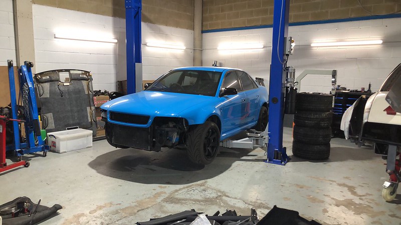
Here's how it looked when I collected the car:
Now it was in my posession it was time to make a spec build sheet and work out what components I would be adding to the car:
One the build general specs were decided upon, stage 1 is to strip the car of all in-necessary wiring, brackets and any panels such as the boot floor.

I thought I'd make a post about my build here. I run my own specialist workshop and needed a demo project to use in advertising my business and skills.
As this will be a lot to post in one go (as the car is nearing completion) I’ll make posts over several days. Although saying that, I have started to post this elsewhere - so I have a couple of posts to submit here in one go.
A little about myself: My name is Troy Tempest, those of you of a certain age group may recognise the name from a Gerry Anderson TV show. Given the namesake, the business had to follow suit and it only made sense to nickname the car "Stingray". I studied motorsport engineering at the University of Brighton and worked for a VAG specialist for a little while before moving back to my roots in Nottinghamshire. I then worked for a well known kit car manufacturer before deciding to open my own workshop.
In deciding to build a race car an important consideration is "what do I want to compete in?" - I had my eyes set on the VW Classic Cup, sponsored by the guys at KW Automotive UK. This series, at the time, had a GT class and allowed: 4WD and any VAG group vehicle that was manufactured before 2003. SO, with that in mind I started to look around for what I could buy. I knew it had to be Audi based, 4WD and I ideally wanted a wide body, so that narrowed it down to several models. The B5 RS4 is prohibitively expensive to buy and convert to a racecar and if I were to use a C5 RS6 saloon, I'd have to do the manual conversion. There's also the consideration that the C5 RS6 is a heavier car and the two extra cylinders aren't really needed.
With the criteria in mind, the obvious solution was a B5 S4 sporting the RS4 widebody conversion - the issue was that all the cars I'd seen for sale at the time were complete, highly finished cars in road trim. To cut the story short, no more than five minutes after that thought passed I saw a post in one of the B5 Facebook groups with a widebody converted S4 for sale as a project. It pretty much ticked all the boxes...
Here's a short run down of the spec list:
- Widebody chassis, freshly painted in Porsche Riviera Blue
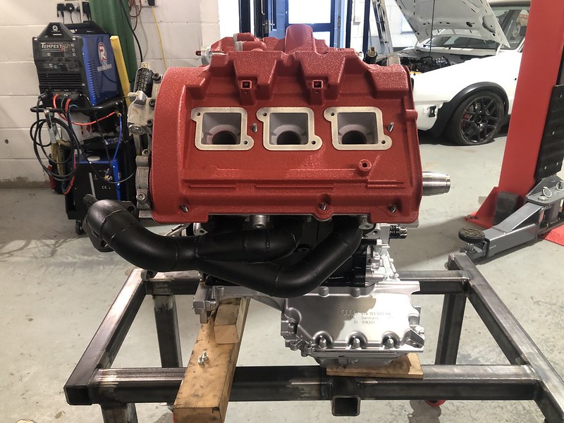
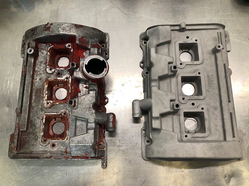
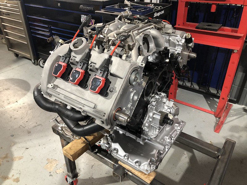
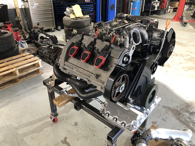
- Freshly built engine with Mahle Motorsport Pistons, Upgraded rods, TDi oil pump conversion, Crank Girdle, 2.8 heads with Rosten Performance valves and titanium retainers, etc.
- TTE 780 Turbos on MRC manifolds
- Fidanza lightweight flywheel
- Gearbox rebuilt with uprated first and second and taller 6th gear - quaife front LDS and 4:1 Torsen torque washers.
That's pretty much the parts that piqued my interest as any interior trim, oil coolers and other parts that came as part of the deal were of no use to myself.
After a few conversations with the owner the deal was done and I went to collect the car.
Here's how it looked when I collected the car:
Now it was in my posession it was time to make a spec build sheet and work out what components I would be adding to the car:
- Link thunder ECU
- ECU Master PMU 16
- ECU Master CanBus Keyboard to control the PDU
- Cosworth/Pi Omega P4 Pro Dash
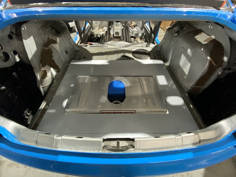
- Pro Alloy 45 litre fuel cell
- -8 front to back fuel system
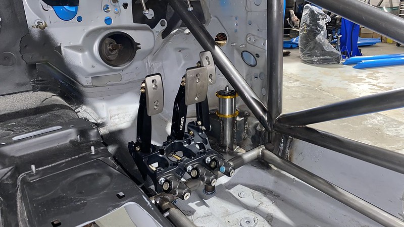
- Tilton 600 series pedal box and master cylinders
- KW Competition 2 Way dampers
- Air jack system
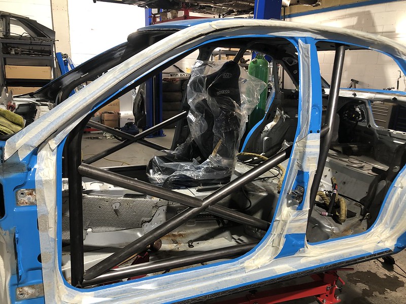
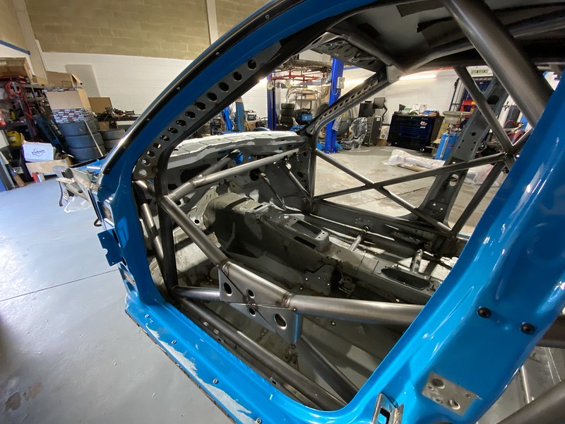
- Custom Cages BTCC STC spec roll cage
- Aerodynamic package including large single element rear wing.
One the build general specs were decided upon, stage 1 is to strip the car of all in-necessary wiring, brackets and any panels such as the boot floor.