Sootpig's A3 track/drag car

No worries mate, I don't mind sneaking something on the punch for you mate, it's a decent piece of kit! Also powder coat it white maybe? Is it just a face plate you want or you wanting a full box making? Could design something with some some lazy fold stitching on it and tab it together after paint
That's very good if you to offer, thanks mate, i'll have to make a drawing up regardless (i'm a bit useless at CAD) but i'll give it my best go. I had planned on making it out of aluminium, but thin steel would be fine also.

Just a face plate really. I'll be welding bars from the main bar down to the transmission tunnel to bolt/weld the plate too.

Like most things on the car, i have a rough idea in my head how I want it to look/how to do it, but it depends on the resources avaliable at the time. I sometimes get half way through a job, then have a complete change of direction because i've had a better idea/hit a wall. The switch plate will be no different :D
Really admire your skills here! Wires are my worst enemy but slowly I'm getting better.. (After wiring up my headlights completely the wrong way haha)
Thanks mate, I have a play with things :)

just think of it as like unpicking a ball of string, but the string is notted, super-glued together, and on fire. Haha

It's really not THAT bad when you start fresh like I have, because you know what all the wires do/where they go. The OEM harness made my head hurt, so it had to go.
 
That's very good if you to offer, thanks mate, i'll have to make a drawing up regardless (i'm a bit useless at CAD) but i'll give it my best go. I had planned on making it out of aluminium, but thin steel would be fine also.

Just a face plate really. I'll be welding bars from the main bar down to the transmission tunnel to bolt/weld the plate too.

Like most things on the car, i have a rough idea in my head how I want it to look/how to do it, but it depends on the resources avaliable at the time. I sometimes get half way through a job, then have a complete change of direction because i've had a better idea/hit a wall. The switch plate will be no different :D

Thanks mate, I have a play with things :)

just think of it as like unpicking a ball of string, but the string is notted, super-glued together, and on fire. Haha

It's really not THAT bad when you start fresh like I have, because you know what all the wires do/where they go. The OEM harness made my head hurt, so it had to go.

I'm pretty ok with 2d cad so I can always neaten it up a little if needs be! Well if you have a mixture of ideas about the face plate then design a few and I can make a few for you, we do have 0.5 aluminium but it's expensive and high reflective (for light fittings) so 0.5 or 0.7 steel is the option! It's the way with anything mate, I always change my mind last minute I did it when buying my car, nearly bought a tdi and then grew some balls and got the 2.0t petrol instead Just let me know mate
 
  • Like
Reactions: Sootpig
I am in absolute awe of you overall skills in all areas of this project.

people feel so proud when they follow a guide to build a Caterham what you have done is amazing in comparison.
 
  • Like
Reactions: Sootpig
subbed, awesome read mate well done.

Thanks bud :)

I am in absolute awe of you overall skills in all areas of this project.

people feel so proud when they follow a guide to build a Caterham what you have done is amazing in comparison.

It's really nothing anyone couldn't do with a bit of time and patience (and money...), I enjoy having no guide or plan. Making it up as I go along is the best part :D

Thank you to everyone for the kind comments, It really spurs me on to do bigger and better things to this car. The positive feedback I've received is truly heart warming :)

It's that time of the week again... Update time.

Picking up from where I left of on Saturday, I finished off the heat exchanger piping, I made an adapter by cutting up the scrap aircon pipe I had. A bit ugly, but it works...


The big end goes to the plastic T housing from the engine head and the smaller hose goes to the heat exchanger.

I happened to have a gland that was JUST big enough to pass both coolant hoses through. It's not quite how I wanted to do it, but I may re-visit it next time the engine comes out and look at using some kind of quick-release connector.


the short length from the exchanger to the ballvale is just temporary until I work out exactly where I'm going to mount he valve on the switch plate. The heat exchanger works really well. but I'm going to need some higher CFM fans.

Then I fitted some switches to my steering wheel


The two red ones (they glow red when ON) will be nitrous armed and anti-lag/LC. The white one... I'm not sure yet...

Then I added more buttons!


Logitech aint got nothin' on me.

The bottom one will be for the horn... The other 2.. I'm not sure yet (might remove them). Then I went to bed.

Sunday morning I opened the passenger door and decided... Today's the day the bitumen goes.


Ok... here we go.


That wasn't so bad...


All right....


Phew! what a mess (I was pretty exhausted by this point)

The carpet stuff (I called it chewbacca's pubes) was a nightmare to remove.


I used swarfega Jizer to remove the tar (I brought the stuff because the name made me laugh, but it was really handy for removing the tar residue). A few hours and a lot of scrubbing later:


Ended up with a whole bucket's worth of weight saving


I haven't weighed it, but I'd guess about 8Kg.
 
Then I moved my attention over to the passenger door. More specifically, the electrics. My issue is I want to fit all switches on to a central switch plate. The OEM window switches/wiring don't fit into my plan, so they get CHOPPED!

I took the window motor apart and soldered wires directly to the commutator and remove the control circuit (no longer required)


Re-fitted the motor, sleeved the wires and put them in to the cabin, but not before testing the motor on a power supply, because why not...


I'll be using a double poll double throw momentary switch. Which basically means it stays in the middle, you push it up, the window goes up, you push it down, the windows go down. But there is no control circuit/protection*. So if you're a moron, you can burn the motor out. I don't plan on holding the switch down and chuckling while smoke pours out of the motor... *common sense required.

Then I continued a job I started weeks ago, and fitted the locking solenoids to the passenger door and the boot


And that was that for sunday night.

I did however pick these Siemens Deka injectors up from Carl. One of them's not flowing right, and was 10% out when he flow tested them, so I took em in to work, and chucked em in the ultra sonic cleaner for half an hour, in Isopropyl alcohol. No idea if it'll work, but no harm in trying.


  • Like
Reactions: Cambaines and superkarl
Awesome project/progress bud
Little tip for removing the bitumen residue is diesel (works a treat)
Thank bud, I'll bear that in mind. The jizer stuff worked well (and doesn't stink of diesel) but its nice to have a backup plan :)

I got a bit more done on the car last night. Got the drivers door to the same state as the passenger door, modified the window motor, run the wiring for the central locking actuator in to the door and mounted the control module.

Hopefully will have the central locking totally wired in before the weekend.
 
Ran the wires across to the passenger door and then off to the boot (control module is above the bonnet release handle)


While i was at it, i ran the wires for the high level brake repeater.


added a permanent live feed in the fuse box to the central locking box


Soldered to the back of one of the main feeds, as lack of forward planning and spare crimps, meant i can't re-do it. This will be perfectly fine though. I daisy chained another fuse in too, so the two fuses on the right hand side are permanently live, the rest are off the main ignition relay, and the 4 along the bottom feed the 4 relays.
 
I hope your aircraft installations looked different from the back of that fusebox :p
Great work mate, huge progress.
 
  • Like
Reactions: Sootpig
I hope your aircraft installations looked different from the back of that fusebox
Great work mate, huge progress.
Haha yeah admitedly it's not very tidy under there, but that's the trouble with making something totally bespoke and on the fly, it's not going to be as neat as production work, and still very much prototype stage :)

Fortunatly, i thought ahead (for once) and made the plat just so that you wont see any of that birds nest when it's done
 
Not going to lie Adrian, that really was pretty dull :laugh:

Great work though mate. Impressive stuff.
 
  • Like
Reactions: A3-Lee and Sootpig
Not going to lie Adrian, that really was pretty dull

Great work though mate. Impressive stuff.
I aim to please :'D

Thanks man

Last night i spent an hour working out the wire functions for the rear light clusters, and began wiring them up. Not going to bother re-pinning the light cluster connectors, just going to butt connect to the factory wiring at the boot end and run new wires. Probably use 6 core multicore cable, for simplicity's sake. I need feeds for brake, sidelights, indicator l/r, reverse and fog.

Dont really NEED to do all this, as the car probably wont be going on the road next year now (i'm planning on getting my trailer licence and towing it)

But if you're going to do something, might aswell do it properly....
 
  • Like
Reactions: StaceyS3 and Erikn89nl
Not got many pictures from this weekend, but i did get quite a bit done sunday afternoon.

My new boost gauge arrived, which kinda-sorta matches my VDO fuel gauge. I would have got a VDO boost gauge, but the ones that show vac only go up to 20PSI, which wont be very uself to me.


I managed to finish running the wires for the read light clusters to the front of the car. Brakes go to the pedal, reverse to the gearbox and the rest will be going to the switch plat which i haven't even designed yet.

Then i spent all of sunday afternoon slumped over the transmission tunnel, swearing at this mess:


I decided i would 'finish' the fuse/relay wiring, and add all the trailing leads ready to go off to the switch plate/lights/whatever so i could bolt finally bolt it down, and i got pretty close to doing that. All the relays and fuse slots are now wired up, with some functions yet to be allocated.

No doubt it'll be coming off again soon, but i'm happy that it's 90% done. Pig of a job. Fiddly, awkard position to work in, and no one will ever see it.

Also mounted the USB power supply underneath the ECU.
Dear mother of god that looks messy under there


It will look much neater once its finished and i can tidy everything up. No more pictures as its just adding wires, which takes so much time, and doesn't really look any different after 5 hours work haha.
 
Made a coily, springy, stetchy wire thing today. This will go between the steering wheel and the rest of the car for my switches/push buttons. I wanted black cable, but i had this lying around, and it's got 8 cores, which will give me supply, ground, and 6 switch feeds.


I looked on ebay for a coiled cable for such a purpose, and one guy wanted over £15 for 2ft of cable! Noooo thankyou so i set about making the one you see above.

Quite simple really, you find yourself a metal bar, with the rough diameter you want for the coil, wrap the wire around the bar tightly, then heat it up and down with a heatgun, just until you see the sheath go glossy.

Once it's all nice and warm you give it a good squeeze/twist and let it cool, then coil it off the bar, and tadah, coiled cable.

Its a bit old skool, but it's a simple way of having electrical connections to a moving part, without the need for slip rings, clock spring, or some kind of fancy wireless/magnetic fiasco.

Should look somert like this when it's all said and done, only, ya know, not so professional.

 
  • Like
Reactions: SamHendry and limbo118118
Another painful weekend of contortion reminds me I'm getting too old for this (i'm only 25... haha)

Seats are now in! started with the passenger side, so I could get a feel for where everything was going to sit, before I attempted the drivers side. I decided the easiest way was to bolt the seat brackets to the seat runners. I did the passenger side first to also see if this would be strong enough...


I also made a mount for my battery isolater and (badly) welded it to the transmission tunnel, just by the handbrake.


Once I had the passenger seat roughly where I wanted it, and was happy with how sturdy it felt, I copied the position for the drivers seat. Turns out I need to move it forwards a few inches to comfortably operate the clutch, but that's just a case of drilling a few more holes.

View of the isolator from the driver's seat;


And the final result;


Pretty happy with how it all worked out :)
 
  • Like
Reactions: Donny_DJ, A3-Lee and Prawn
Waaaaaay over-due an update. I just haven't had the time lately to get on the car, and have other distractions, but fear not, I'm back and I'm ready for action!

Over the Christmas holidays I started to change the configuration of my ECU. I'm upgrading it from a MS3 to an 'MS3X', which taps the full potential of the processor. Allowing fully sequential fuel and spark on up to 8 cylinder engines. it also gives me;

  • 6 programmable medium current outputs (can be used for boost control, pwm idle control, relay outputs... whatever i want.
  • 4 switch inputs, switch tables, start data logging, launch control...
  • Cam sensor input (required for sequential fuel)
  • 3 extra analogue inputs (could be used for additional sensors, anything that outputs a voltage to the ECU)
I have also decided to add the internal knock sensing module to my ECU, which provides sophisticated programmable knock detection (you can select different ****** conditions, and whether it detects per cylinder or not) I'll be a lot happier tuning the engine knowing the ECU is watching to make sure i don't get too silly with the timing table...


So the first thing to do, was take the ECU back out the car, and remove all the modifications I made, when I built it. The reason being, at the time of assembly, I planned to keep it simple and run batch fire injection and wasted spark ignition. Plans have changed, I'm still going to be using a Ford EDIS coil in wasted spark for now, but the 'igniter' MOSFETs will now be located near the coil, instead of inside the ECU itself, which has a few advantages IE shorter high current paths, and reduced electrical noise inside the ECU. The injector drivers were also removed, as these are now handled by the expansion board.

The MS3 main board with mods removed, and components returned to their original positions;


Added the Knock module to the MS3 CPU board (SPR3 + SPR4 are now my knock sensor input pins)


Trial fitted the MS3X board;


Was pretty happy with that, so called it a night, and the next morning I started pulling apart the wiring harness I made previously, and began figuring out where all the spaghetti needs to go.

Knock sensor wires salvaged from the OEM loom;


I have two non-interchangeable plugs, so they cannot be plugged in the wrong way round. one Is used primarily for sensor inputs and outputs from the MS3 main board, the other is used for injector outputs, and other functions from the MS3X.

On the left is the injector wiring that i have just moved over to it's new home on the 'MS3X' plug. The Violet wires are +12v supply, the green and blue wires are the individual injectors that ground through the ECU FETs, turning them 'on'.


Then there's the other side of the loom, that goes from the bulkhead plug to the ECU. This time I didn't buy a pre-made harness, so I got busy with the soldering iron;


The wires grouped in the sleeving are the 4 grey wires for switch inputs (steering wheel) the other 4 are logic level spark ouptuts. Like i mentioned earlier, I'm sticking with wasted spark for now, so only really need 2 spark outputs, but I chose to run the other 2 wires in case I later decide to go with a COP arrangement, or some other type of fully sequential spark.

Buttoned it all up and it looked like this:


Punched a fresh hole in the ECU plate and fitted a grommet;


You might recall I said I fitted the knock module, and SPR3+4 were the inputs, well... SPR4 used to be used for SPARK B output. Which means I had to un-pick the ignition wires that went to the FORD EDIS coil in the bulkhead to remove the wire.


With the wire removed and fitted into it's new home in the MS3X bulkhead plug, I decided that was a good point to call it a day, and took some more pictures of the car, just to remind myself what it looks like...


Thanks for reading :)
 
  • Like
Reactions: sparrow and StaceyS3
Just read from the start!

Dude you have some electrical skills!!! Good work, looking forward to watching this progress!!
 
As above your electrical skills are top notch, nice progress.
 
  • Like
Reactions: Sootpig
interesting project dude :)
Thanks man :)
Just read from the start!

Dude you have some electrical skills!!! Good work, looking forward to watching this progress!!
Thanks for taking the time to read my ramblings :)

To be totally honest, 90% of the time i have no idea what i'm doing :D
As above your electrical skills are top notch, nice progress.
Cheers mate, comes from doing it as a profession i guess :)
 
New years eve update!

MS3X is in and running fully sequential and injection AND fully sequential ignition.

Had a bit of a change of plan again, and decided to rip out the Ford EDIS coil in favour of the original COP system. Why? Because to drive the EDIS coil i would need to use an external coil driver. I was going to use the Bosch driver, which got me thinking why not use the COPs and have a fully sequential setup using the OEM hardware (glad i ran those extra wires now...)

Anyway, the first thing i needed to do to run fully sequential was add the cam position sensor to the ECU. Removed pins and re-made the connector using new crimps


Then buttoned it all back up with conduit


Niiice!

Tapped into the 5v ref feed for the Cam sensor from the throttle position sensor 5v to save running another wire.


Put the AIT, CAM AND TPS wires into conduit to protect them, as they run very close to the block and could easily get damaged.

Looked up the wiring for this guy


Once i knew what wires went where i mocked it up so i could prototype it before fitting it and tidying the wiring up properly.


Got it to start, but it was lumpy as hell, running super rich, and billowing smoke.

Turned out i had the cam sensor parameters set incorrectly. After a lot of head scrathing me and Carl figured it out, and got it running without a cam sensor fault. But it was still lumyp. After more head scracthing, Carl suggested i check the plugs.

They were black as hell where it was running rich, so the fouled plugs were causing issues. Cleaned em up and it idled ok, finally running on all 4 in fully sequential mode :)

Came up with a super crafty/lazy way to mount the coil driver


Made a metal blanking plate up and drilled a hole for a grommet to pass through.


And thats all for now. I will continue finishing the wiring. Here's what the engine bay looks like now;


Happy new year everyone!
 
  • Like
Reactions: SamHendry
More progress. Mainly headlight wiring going in. No massively important to the running of the car, or fun to no. But its just something i need to get done and out of the way...

However, new years day (while still partially inebriated) i decided to repair my laptop. The power connector MELTED into the psu plug, rendering the whole thing useless. The hing was also broken, making the screen floppy and vaunerable. The laptop is 10 years old, but reluctant to retire it, and being a little 'merry', i came up with this;


I'm please to report, even after drilling through my laptop screen, it works rather well

On to the 'real work'

Finished off the ignition driver wiring by crimping the ecu logic wires directly into the plug, grounding the middle pin, and running them through the bulkhead blanking plate via a grommet.


Taped up the main 'spine' of my bespoke engine loom (hopefully i wont need to add any more wires, but it can be undone and wires can be added if i ever need to).


Fitted the horn behind the front bumper and made up the tails of the headlight loom. (Horn feed taped up with the FL headlight wires)


These will go through in to the scuttle panel, along, and then down into the drivers footwell with the FR headlight wiring. I coud have kept the run shorter and gone in the passengers footwell, but there's all ready a lot of wires there, and no easy pass-through into the cabin without drilling holes and creating a potential leak-point.

Headlight and horn are gorunded at the chassis. Which isn't the true purists way to do things. Ideally, they'd be grounded at a central point. But this will work perfectly fine, and keeps the wire countdown.

 
Didn't get as much done tonight as i wanted, but productive none the less.

Figured out the wiring for the sunroof module and ran the wires for that (reading lights and motor)


Labled up some of the wires so i know where at least some of them go hahaha.


Took the ECU/fusebox plate off again to remove the fan relay, added another relay in its place to supply the headlight wiring (over-sight on my part) and have moved the fan relay down to near the fans.


That was yesterday night. Tonight I fitted some Siemens Deka 630cc injectors. Waaay over-kill for my current turbo setup (will flow enough for about 450HP) but it's future proof atleast.

Just goes to show the versatility of a standalone ECU when I can tripple the injector size and have the engine idling sweet within one hour.

Idle on the 630's


Took a little bit of map fettling to get it to stop hunting, but really not too bad. I also managed to foul the plugs again, as I forgot to connect the MAP line to the ecu. Took the opportunity to swap them out with some NGK 7's (colder plug)

And that was that. More progress to follow soon (really trying to crack on with this now)
 
  • Like
Reactions: StaceyS3 and sparrow
if you want to label all of the bits of your loom, have you thought about getting a labelling machine? they're not particularly expensive and will be harder wearing than masking tape!

amazing work on the car - its proper cool that you have put your own stamp on the car by redoing the wiring yourself, and of course, putting the ecu together and mapping!
 
  • Like
Reactions: Sootpig
if you want to label all of the bits of your loom, have you thought about getting a labelling machine? they're not particularly expensive and will be harder wearing than masking tape!

amazing work on the car - its proper cool that you have put your own stamp on the car by redoing the wiring yourself, and of course, putting the ecu together and mapping!

Thanks mate :)

Yeah I do have a labeler at work, it was just a quick way of being able to reference the wire colours hen it comes to wiring up my switch plate. I have it all written down in a notebook, it's just easier to look on the tape :)

--------------------------------------------------------------------------------------------------------------------------------------

Forgot to mention yesterday, Carl pointed out a pretty massive fail on my part.

TunerStudio has a tool under the VE table window that allows you to generate a generic fuel map based off your engine size, engine setup (ie Turbo charged with intercooler) ect, just to get the engine running, ready to tune.

Now one of the things it asks for is your peak HP figure, and at what manifold pressure you expect it to make it at. I have a K03 at the moment, so I expect about 18PSI peak, and 180HP or thereabouts. So i proudly bashed in 124Kpa (18PSI) in and generated my table. COMPLETELY disregarding the fact it's asking for ABSOLUTE manifold pressure, as in atmospheric pressure+boost pressure
rolleyes.gif


So I was telling the ECU I expected to make 180HP at 3.4PSI of boost.

Which is why It wouldn't rev for shoot, as soon as i revved the engine it was trying to put in enough fuel for 180HP
whistle.gif


It's a steep learning curve... bare with me.
 
  • Like
Reactions: SamHendry
More updates from over at racecar HQ.

Today we tackle the thing i've been putting off for a while, simply because I'm not sure what I want or how I want it.

So, as is tradition with this build, I jumped in feet first and just started manipulating metal until it looked somewhere near what was in my head.


That's a start (The aluminium actually started life as a magazine/catalogue shelf, the bends were all 90*, and i bent them to suit my needs. Re-cycling, don't ya know. This is a responsibly sourced, environmentally friendly racecar).

Then I looked at how i was going to mount my progressive nitrous controller, and the top of the plate, and settled on this rough position;


Drilled and tapped the angled steel bar. Then bolted it to the aluminium and tac welded them in-place. Doing it this way ensures perfect fitment.


Marked the plate up roughly while sat in the seats, to get an idea on leg clearance, then took it over to the bench to plasma cut the corners out (first time i've used a plasma cutter properly).


Which looked something like this:


Not a big fan of the s**t stained aluminium look, I decided to go for a brushed finish.
http://vid1207.photobucket.com/albums/bb469/sootpig/A3 Track project/20160110_102042_zpssvpxwopm.mp4

Few minutes with a stainless steel brush, and it looked a lot smarter (but still dirty)


Made some little brackets up to mount the NOS controller. Didn't take any pictures of the fabrication of these, but it's nothing fancy. Just some re-purposed steel plate, cut, bent and drilled. Rounded the edges by lopping the corer off in a guillotine and finishing with a sanding wheel in the angle grinder.


Then I mocked up roughly where the nitrous bottle was going to sit. Settled on mounting the bracket with rivet-nuts just over the rear axle. Wont require the fuel tank doping, it's nice and level, and i'll be able to reach the valve from the drivers seat.


Several parts/tools are now on order to make the fabrication of the switch-plate a lot easier (52mm hole punch for the gauges, for example)

Going to the Autosport show this weekend, so I don't expect to have much of an update until next week now.
 
  • Like
Reactions: StaceyS3
All looking good Solly!

Very jealous of your electrical skills, it's an area that I just about cope with, but don't enjoy at all!

I've got to make up an ECU extension cable for mine shortly, and it's not a job I'm keen on at all!
 
All looking good Solly!

Very jealous of your electrical skills, it's an area that I just about cope with, but don't enjoy at all!

I've got to make up an ECU extension cable for mine shortly, and it's not a job I'm keen on at all!

Cheers Prawn!

Yeah the electrical thing is a bit of a pain in the ***. But i'm glad i could remove the heavy oem harness.

Where i really struggle is the fabrication/welding side of things. I can get by, but i'm not as good at is as i'd like to be. Luckily this is not high precision work, so it doesn't matter too much, but my OCD starts flaring up if it looks messy

Whats the need for the extension? Re-locating the ECU?
 
Id like to move my ECU inside the car yea, so need an extension around 2m to bring it in in a sensible place to allow me to mount the ecu on the tunnel.

I have the male and female plugs for each end (thanks to Rich!) it's just a case of sourcing the appropriate wire and doing all the soldering / wrapping.
 
Made some good progress over the weekend. I'll keep it short and let the pictures do the talking.


Batt isolator pull cable fitted


NOS Bottle bracket mounted


WON Max Extreme progressive Nitrous controller wiring harness terminated on the back of the switch plate;


Made a bracket out of steel for the soleniods (it's a bit rough, but because racecar.)


mocked it up for fitment check


Then gave it a lick of paint


Fitted a new plug to the solenoids, as the old bullet connectors from the kit's previous life looked a little... shagged.


Then I moved my attention to 'La piece de resistance', the switch plate.

marked up gauge holes


used a step drill to get a big enough hole for the 52mm punch


Which left me with a nice, clean, accurate 52mm hole to mount gauges in.


Then some more, marking, punching, drilling....


and some more....


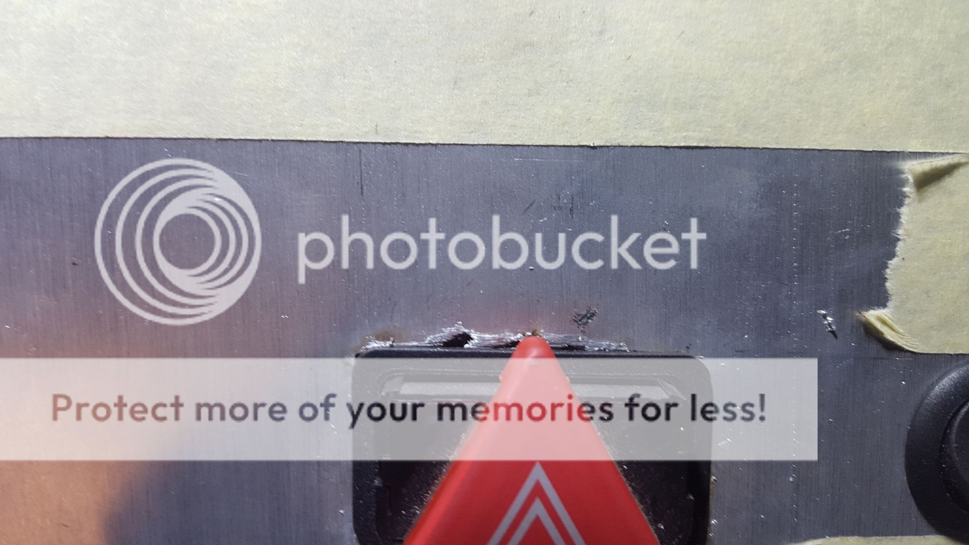
Then I had a tricky one to do... a rectangular hole for the hazard switch, which only has a small lip, requiring a rather accurate hole. After weighing up my options, I settled on plasma cutting it, and hoping for the best (I'm not very experienced at plasma cutting at all.


Undersized the hole, and opened/neatened it out with a flat file (post picture). Work rather well! apart from the little slip I had (Had to be at the top, didn't it!?!?)


ordered a Golf/Bora switch, as it will look better.
 
The slip up;


Whoooops! Oh well. After kicking myself for 15mins I manned up and carried on. Fitted more switches (you can never have enough switches...) Then did some wiring for the switch lights (LEDs come on with their corresponding switch, and the coloured switched illuminate when tuned on.


View from the drivers seat:


Safe to say I'm pretty happy with how it's shaping up!

For anyone interested the lights will be wired like this;

Black - ??? Maybe turns all lights off
Red - Rear Fog
Yellow - Front Fog
Green - Side Lights
Blue - Dipped Beam

The two switches above the light switches will be for the electric windows, and the toggle switches will be for various functions like Nitrous armed, radiator fan by pass, cabin fans, other function suggestions? Ejecto-seato cuz?
 
  • Like
Reactions: StaceyS3 and sparrow
Got a little more done this weekend.


Switch plat now has a few extra holes, and some wiring. Decided to go for two more gauges, these are provisionally for oil temp and pressure, but i may end up getting an EGT gauge or something. You can never have enough gauges.


The silver boost gauge is just the old one from the car, for a visual ref.


Still need to add a few things like indicator repeaters, alternator charge light, etc.


Fitted a small relay board (designed for use with arduino) to the switch plate. This will be used for horn and nitrous armed functions from switches/buttons on the steering wheel.


Window switch wiring;


I prototyped the wiring for the hazards and indicator wiring. Hashed it and got it working with just the wires twisted together, but when i actually crimped everything up and wired it in 'properly' and now it doesn't work. I've probably ballsed up somewhere, but I ran out of time, so I'll look at that in the next few days.


I spent quite a bit of time today, helping/hindering Carl with his big turbo MK2 build


He's going to be way over 400HP, so should be fun to watch, gunning for that illusive 10 second pass...
 
Some progress!

The switch plate has had some what of a revision. It dawned on me that i had no easy place to put a connector for the steering wheel coiled wire.

My solution was to weld plates to the sides of the switch plate. Now as I have mentioned several times during this build, I am not much of a fabricator, cutting and welding metal... I love doing it. But i'm not great at it.

Cut the plates


Tac welded them in place.


Looked a bit like this:


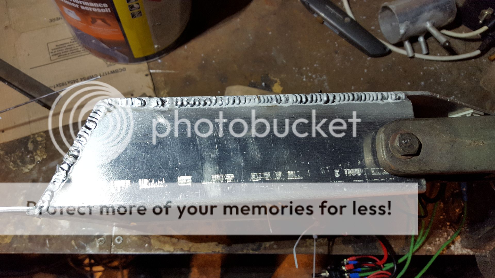
Decided to butt weld it along the seam, for strength and neatness. Had a few slip ups, but bear in mind i did this between 9-11PM after a full day at work... #MidnightOil.


Called it if for a night, then the next evening I finished the job;


Seamed it up


Which sits a little bit like this


Perfect position to take a coiled cable to the copious amounts of switches, buttons etc on the quick release steering wheel.
cool.png


Oh and I got the hazards/indicators working.

http://vid1207.photobucket.com/albums/bb469/sootpig/A3 Track project/20160131_144626_zpsbljvlla7.mp4
 
  • Like
Reactions: sparrow and Cambaines
A post so nice you posted it twice :hearteyes:

Lovely work mate. I am so envious of your electrical ability!
 

Similar threads

Replies
26
Views
8K
Replies
40
Views
4K
Replies
6
Views
4K
Replies
10
Views
3K