Prawn and BigAls A3 Track Car

Did you have to change the compensation in the cold weather?

I killed 2 sets of plugs (7's and 6's) this winter already, she never gets upto a decent temperature on my 30 mile commute in this weather and runs rich as fduck as a result.
 
Change the compensation for what Ant? Fuelling based on ambient temps?

The emerald has a full set of tables for temperature control, with adjustments for ambient temp, coolant temp, and IAT, through warm up, overheating etc, including intitial prime etc.

I've not had to change anything and it's still starting / running /driving sweet as a nut
 
Did you have to change the compensation in the cold weather?

I killed 2 sets of plugs (7's and 6's) this winter already, she never gets upto a decent temperature on my 30 mile commute in this weather and runs rich as fduck as a result.
If it's not getting up to temp in 30 miles, that would point to a cooling issue. Stat stuck open maybe?
 
Not finished what I'm doing yet, but here's an initial teaser :racer:


That -3 degree target will not be an issue!
 
  • Like
Reactions: bigal 1, feck_on_a_stick, RobinJI and 1 other person
Right then, it's just over a week to go until Donington. I should really hurry up and get this back together!

Last weekend I made a start on the mk2 TT ball joint plan.

First up, check and measure what's happening currently before making any changes.

I made a highly technical camber gauge, and tested it on a highly accurate surface :laugh:


In all seriousness, I am 100% confident in the accuracy of this. I've tested it on known level and vertical surfaces and it reads 0.0, and I've of course tested it each way up with a view to taking an average of 2 readings, but pleasantly found identical readings when reversed, so I'm confident that for what Im doing this is plenty accurate enough.

To my surprise, I found I actually had more camber than I had thought:


-2.6 and -2.9 degrees. a fair bit more than I thought, but 0.3 degrees difference isn't ideal, and both sides were maxed out totally, so there was no scope to even them up within the range I wanted.

Still, this confirmed I had less work than anticipated to get to my desired even -3 degrees on both sides.

Next up, car on blocks, and splitter off. Seem here hovering over the pit:


I whipped the wishbones off, and gave them a clean.

Years ago, in a hurry to get things done before another Donington track day, I'd been forced to fit standard rubber front bushes in the wishbones, after these powerflex ones didn't arrive in time:


The old ones popped out easily enough after drilling around the bush with a 4mm drill bit, then I cleaned up the internal faces, applied the powerflex supplied grease, and popped the new poly bushes in:


I doubt these will make a huge change as I've already got the much sought after early 30mm arms, but any added stiffness here has to be a bonus.

I also inspected the super pro rear offset eccentric bushes, and I'm pleased to report that after 3 years abuse they are still in great condition. I pulled them apart and cleaned and regreased them too, for good measure.


On to the interesting bit!

Knowing the mk2 Ball joints needed modifying, I was prepared:


I offered the TT ball joint up to the wishbone, and as expected, 2 of the bolt holes lined up perfectly:


I did briefly toy with the idea of canting the whole ball joint forward, gaining even more caster, like this:


A nice idea certainly, but I opted not to for now. Doing so would push the wheel forward an additional 10mm, which when combined with an increase in track width would almost certainly lead to tyre / arch interface that I'm keen to avoid.

It's good to know it's an option for future though should I feel the need for even MORE caster ever.
 
  • Like
Reactions: snowy, superkarl, StaceyS3 and 3 others
I marked up where to grind away on the ball joint:


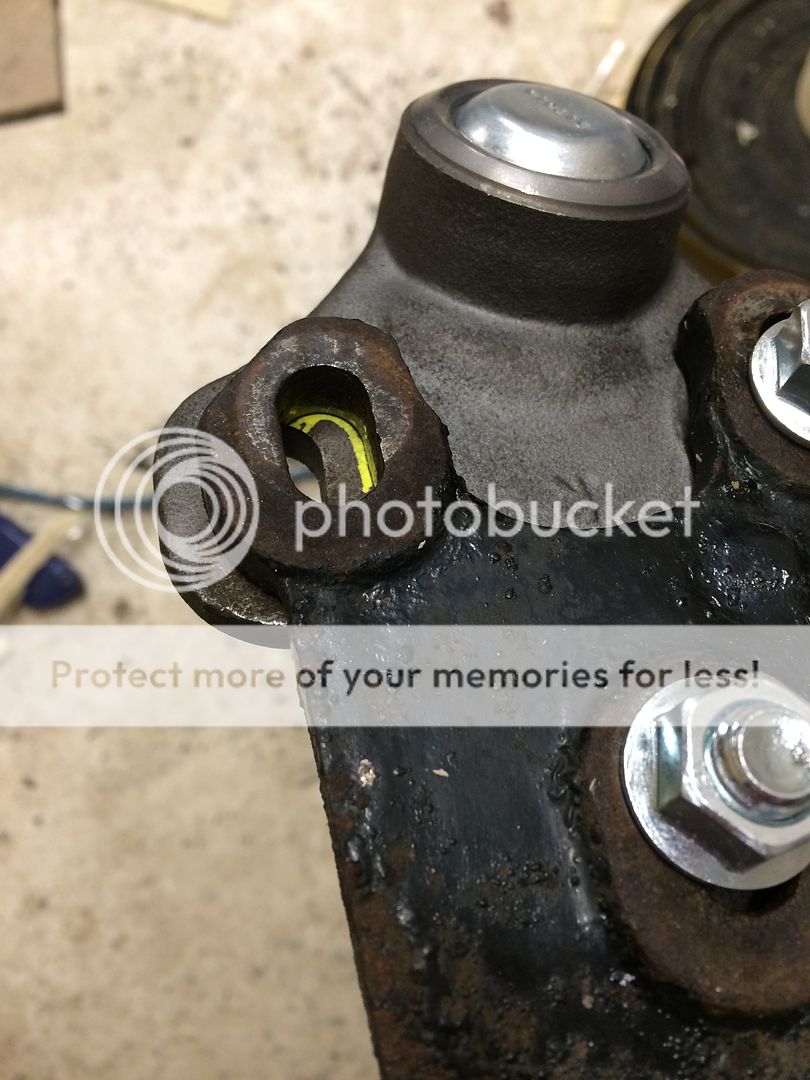
Then got busy with the dremel and carbide burrs:


I've been suffering from this all week, as the tiny steel splinters seemed to get EVERYWHERE, mainly in my hands, and I've been finding splinters all week!

With this done on both joints, I bolted them up, and paint pen'd the bolts to enable easy checking in future:


In Hindsight, I wouldn't have bothered torquing / paint marking the bolts at this stage, as I'll end up adjusting them further before first use.

And here we have one pair of wishbones, new front bushes, and mk2 TT ball joints ready to go back on:


Wishbones back on, with brand new bolts, and all torqued up to 52lbft +90 degrees, then paint pen marked again:


I put the wheels back on, lowered the car back to the ground, and stood back to see what I'd created :racer:


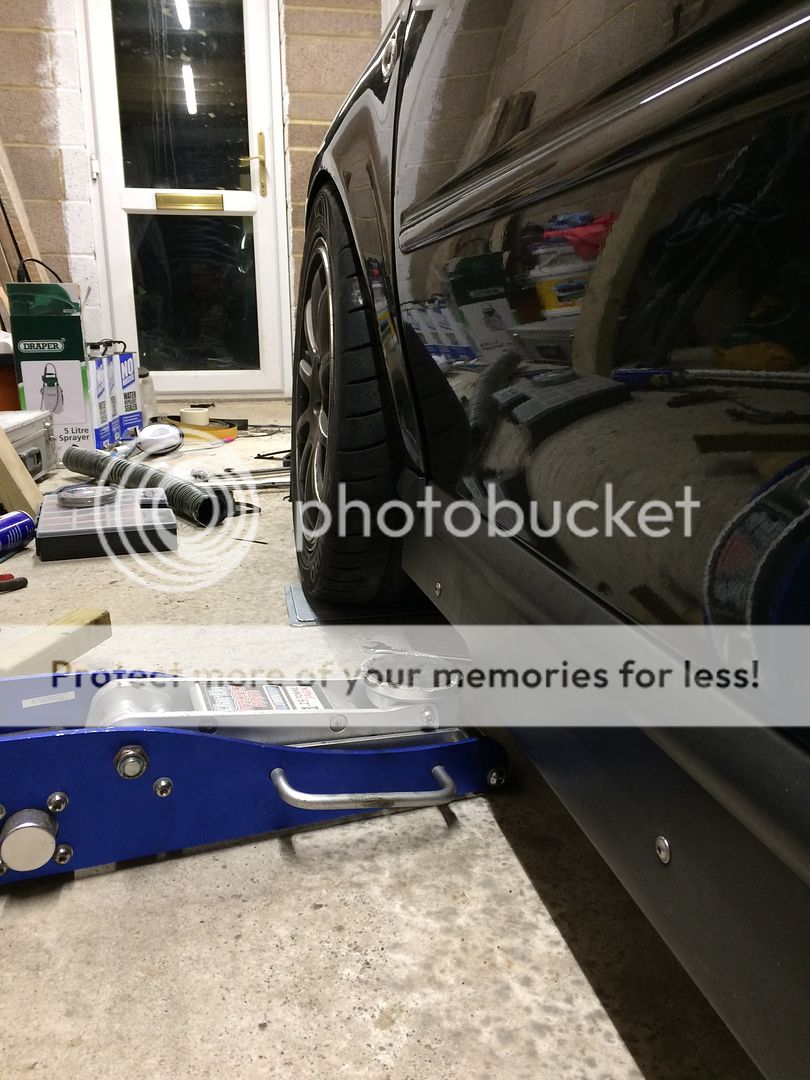
First thoughts - it looks WIDE.

Quick camber check:


-4.4 degrees on one side, and -4.6 on the other!

:sign wow:

Having pushed it outwards at the bottom of the hub, the whole wheel has moved on an outward arc, so the track width at ground level is probably a good 30mm wider than before, and this really shows then looking at the front wheels from behind. there is a lot more tyre visible when looking down the door line.

As a result of pushing the ball joints outwards, tracking has obviously been thrown off too.

Not by a little bit, but probably by a good 10 degrees each side. The wheels really did point like this: \______/ to the point where I couldn't actually roll the car forward or backward at all, such was the resistance.

Moving the steering with the car on the ground is incredibly stiff as I'm sure you all know. With lots of added caster, and sticky 235 tyres, and a small steering wheel, mine is even heavier than most.

I've seen these done before by others, and decided now was the time to make my own:


2x galv plates, with some CV grease smeared over them:


Placed in front of the wheels, and the car rolled forward onto them:


They are fantastic. With the car on the slide plates, I can turn the steering wheel as if the car were jacked up, with absolutely no resistnace at all.

This means that as I'm adjusting toe the wheels are free to turn, and not binding with the ground, so I should get true toe repeatable toe readings.

Keen not to consign myself to an early grave, I decided to investigate track rod thread length, rather than simply wind the track rods out until the tracking was correct.

There was every chance at this stage, that without this check, I could have unknowingly wound the track rods to within a few threads of the end, and one heavy wheel impact could have seen us lose all steering. Not something I wanted.

I unwound both track rods fully until the came away from the rod ends, and counted 23 threads of engagement on each track rod.

I consulted google, and a few peoples who's opinion I value, and decided that minimum thread engagement of 10 threads was the least I'd be happy with.

I wound each track rod 10 threads into the rod ends, and just on a visual, it appears to now be slightly toe in, so I'm satisfied that when it's aligned properly I'll have more than 10 threads in each rod end.

Next up is to make up a DIY alignment rig, using fibreglass garden canes and some bright orange fishing line :)
 
  • Like
Reactions: Jay A3, scotty_24, desertstorm and 4 others
I've been suffering from this all week, as the tiny steel splinters seemed to get EVERYWHERE, mainly in my hands, and I've been finding splinters all week!

Magnet - placed next to where you're drilling/grinding - all the swarf will be attracted to it and not fly about
 
  • Like
Reactions: badger5 and jojo
Operation DIY continues!

I started by replacing the bolts / washers on my Silver Project top mounts for some fresh stainless ones, And marking where they have been set for so long:


Having -4.5 degrees of camber at this point, I rotated the top mounts to gain more caster:


This resulted in an even -3.6 degrees camber, but there was one large issue I hadn't considered:


The ****** wheels didn't fit any more :laugh:
 
  • Like
Reactions: snowy
I undid the ball joints and moved them inward on the slots as far as they'd go. This brought the whole strut onboard gaining room at the top also.


I checked the camber, and after some very minor tweaking at the top mounts, I was at a good even -3 degrees each side.


To give you an insight on how it's done, you need to set up a pair of parallel lines down either side of the car.

I did this using 2x green garden poles, with neoprene stuck to them to avoid any damage where they sit on the body work.
I then cut and tied 2 lengths of fishing line with loops in each end, at EXACTLY the same distance apart, such that they'd sit tightly on the car supported by the bumper profile at each end:


From here, you need to measure in to the hub centres front and rear, and spend a good while making sure the lines are perfectly parallel to the wheels.

At this point I was seeing a 162mm dip to the front cv centre:


And 184mm to the rear hub centre, showing the rear axle is ~ 44mm narrower than the front.


measuring the rear wheel first, I measure the trailing and leading edges of the rear wheel:

At the rear edge of the rear wheel, I measured 119.5mm


At the front edge, I measured 120.5mm, giving a total of 1mm toe in on the rear wheels.l, exactly as expects.


Up front I set the toe to be parallel, measuring the same figure in both sides of the front rims:


and that's it, just got to refit the splitter tomorrow and take it for anyway drive :)
 
  • Like
Reactions: snowy, ProjecTTrack, <tuffty/> and 2 others
Glad you've achieved what you wanted too with the MK2 ball joints! Some food for thought on the track width issue, would you have been able to flare the arches a bit if needed?
 
I'd be lying if I said I havn't been looking at S3 wings....

In an ideal world I'd pick up a tatty S3 bumper and wings from a breaker.

I'd like to be going for 9'' rims in the not too distant future, and my wings have already been 'massaged' with an arch roller. I'm going to ask Andy if I can borrow the roller again this week to give them some further 'assistance'

In other news, I've also got myself a KnockLink G4 through Badger 5 last week to warn me of any knock should anything untoward occur in the engine.

knocklink-1.jpg


Not an essential bit of kit, but a very nice peace of mind to have.

One question if there are any wiring experts out there:

I intend to make use of the OE looms shielded wiring from the factory knock sensors to the ECU plug, and attach the knocklink at the ECU plug.

These are the instruction on the knocklink:


The AGU knock sensor has 3 wires. 1 knock signal, one ground, and one shield.

However, the grounds are joined, and I believe shared with other sensors.

Here are the AGU ecu pins:


From what I can gather, I can hook the yellow wire to either Pin 60 or 68 as the main signal depending on which sensor I connect to, but for the green wire, the earths from the knock sensors are shared, on I believe pin 67.

Thing is, I'm not sure if pin 67 is the shared ground for the knock sensors only, or for all the engine sensors, and if so, would that effect the reading?

Any thoughts much appreciated. I'm trying to avoid running additional unnecessary sheilded cable through the bay when there is already a nice OE plugged shielded option within the factory loom.
 
I've a spare knock sensor for an AGU motor your welcome to it if you want to test it before hacking yours up
 
  • Like
Reactions: Prawn
Sensor grounds should all be equivalent. I'd try the OE wires first. You can always run a separate cable if needed.

However, the instructions state the knock sensor should be mounted centrally. On the 18.t, there are two knock sensors, mounted in between each pair of cylinders. As long as you're aware that you'll be getting stronger signals from two cylinders, and weaker from the other pair, that's fine.
 
  • Like
Reactions: Prawn
Thanks guys. Good info :)

Alex - you're dead right about the two sensors, I'm aware it'll be monitoring one side only.

After talking to Bill I'm inclinded to use the sensor towards #1 as it's further from the gearbox so should isolate a bit better from transmission noise.

For an ongoing monitoring indication I think it'll be OK in one place. When I make any map changes it's only a minutes work to unbolt the sensor and move location then run again to be 100% belt and braces though.

The plan is to add the pins to the AGU/K6 loom adapter on the ecu plug side so I don't actually have to touch any wiring in the bay at all.
 
  • Like
Reactions: sparrow
Spent a few mins on this last night.

Wires from the knock sensor at the alt end were black, yellow/green, and brown/white

I traced these up to the ECU plug as pins 67 and 68 as assumed above.

Sadly, I hadn't realised but the back of the K6 adapter is a sealed unit, so I'm unable to take a feed from there, so what I'm going to try and do it remove the pin from the ECU side of the plug and solder onto it there which will allow me to heat shrink it too.

I realised last night that the cables from the G4 are all shielded also, and not long enough to reach the ECU plug from where I want to mount it, so it seemed stupid to rush in and complete it in unshielded wire, so I need to source some shielded wire today and have another look at it tonight.
 
  • Like
Reactions: <tuffty/>
When I did the knock sensor wiring on mine, I don't remember the OEM cable being shielded.

I wired mine into an internal add-on knock detection module on the MS3, and with the engine running I get about 5-10% background noise, seems to work fine, but i wont know for sure until i actually get knock under load...
 
I don't know if it matters for the Knock Link but the stock AGU knock sensor reaches a max of 29.835 volts and to use it with older megasquirt you needed a signal conditioner to make it a 0-5v signal.
 
Nick

Why not just buy 2 wire (actually 3 pin) knock sensors

0 261-231-038

Then fit 2 and use a switch to change between the 2. Then you have 2 knock sensors covering 4 cylinders.

12 volt and signal wire is all that's needed.

I used a knock detector I got off ebay for £40 and 2 of the sensors above but had the luxury at the time to compare the knock to the ecu reading to adjust the sensitivity
 
Last edited:
Good thinking Dan.

I THINK those are the sensors I already have.

My AGU sensors are 3 pin. I think me7.5 sensors are 2 pin?

The more I look the more I'm swaying towards adding totally see rate wiring for the knock sensors.

Forgive the silly question, but what sort of switch would one use to switch between feeds?

I've typically only wired in on/off affairs previously :laugh:
 
Single poll double throw would be fine. Middle pin goes to the ecu and the two outer ones to the sensor signal
 
Spdt

Double throw going to single pole.

So signal wires from the 2 sensors go to the 2 throws and single pole goes to device.

I've got a link for the device which has a diagram for the sensors I listed but I can't link so I'll send it over.
 
Very nearly lost the will to live with this last night.

I'm sure I've said it before in this thread, and no doubt I'll say it again.

I HATE ELECTRICS

@Sootpig , how much do I need to pay you to drive to Southampton and sort it out for me :laugh:

I didn't have any old plugs, and my ECU doesn't use the knock sensors, so I chopped off the stock knock sensor plugs to reuse. Making sure to leave enough wire either side to reconnect if I ever need to.

These are the plugs:


Everything I can find online, and also the emerald wiring info, suggests that pin 1 is signal +'ve, pin 2 is signal ground, and pin 3 is the shield.

I wired pin 1 from each sensor to either side of the SPDT switch as suggested above, with the output from the switch to the G4 yellow wire (Signal +) . Then joined pin 2 from each sensor together, and to the G4 green wire (Signal -)

I joined the shield from the new cable to the G4 blue wire (ground), and put that to earth under the dash, and finally the g4 red wire (+'ve) to the switched 12v under the dash.

To my knowledge, that's all exactly as per diagrams.

When I start it up, with one sensor selected, it goes through the process of dim blue, flashing blue cailbrating, then solid green, as you'd expect.

On start up with the other sensor selected, it remains dim blue and doesn't recognise a signal at all.

What's most strange though, is if I start it up on the one working sensor, it'll idle showing the green OK light, but when I select the other sensor, or the middle OFF position with no sensor selected, it continues to show a green light suggesting all is well, which is simply impossible if there's supposedly no signal to it!

ARGH.

I repeat:


I HATE ELECTRICS

 
  • Like
Reactions: craigt1985
I called it a day at 10:45 last night, and frankly I'm F**ked off with it!

I'm reluctant to put all the dash trim back in to allow me to drive it to see if the one side of the switch is working, only to then have to remove it all to rewire if it doesn't work.

I may rewire it all this evening to a single sensor without the switch and see if that works.
 
In other news, since changing to the Reyland discs, front pad wear seems to be CONSIDERABLY better.

On the old compbrake rotors, I'd get 1 day from a set of pads, and be left with around 3mm of material that would do a few thousand road miles, but not another event.

Since changing to the reyland discs, using the same brand F2R pads, I've done 2 sessions at Goodwood, 2 full days at Castle Combe, and a Curby sprint, plus around 3000 road miles, and the pads are around half worn currently! it's an absolute miracle.


Not knowing how long they are going to last, I didn't want to go to Dony without spares, so ordered these up from Finishline, who somehow come in £50 less than anywhere else :)


Also, a very nice chap from Holland has lent me some spare driveshafts to take to save me having to build up the spares I have that need rebuilding. Thanks @Erikn89nl :racer:
 
Also, a very nice chap from Holland has lent me some spare driveshafts to take to save me having to build up the spares I have that need rebuilding. Thanks @Erikn89nl :racer:
Love how you pretend to everyone that I volunteered them!
He is holding them hostage, probably in a van. If you spot him, please call the police!
 
  • Like
Reactions: Prawn
I'm with you with the hating electrics! Haha
Car electrics anyways!
Put me in a power station or wiring lights and sockets up in the house in fine. But auto electrics are just dam confusing haha.

What odd have you Gone for his time around?
 
Sounds like a duff sensor or a duff switch. Try running it with the switch set one way to the known working sensor, then rewire the switch to the other side of the contacts with the known working sensor. That will rule the switch being duff out, in which case the sensor is faulty.

Car electrics really aren't as daunting as everybody makes out, don't get it really. It's just a bit backwards to what you are always taught, because it is normally the ground that switches, not the positive as we are always taught in a domestic situation.
 
Having -4.5 degrees of camber at this point, I rotated the top mounts to gain more caster:

Any ieas how much here ?

That's a significant amount of rotation
 

Similar threads

Replies
26
Views
8K
Replies
6
Views
4K
Replies
10
Views
4K
Replies
166
Views
20K
Replies
40
Views
4K