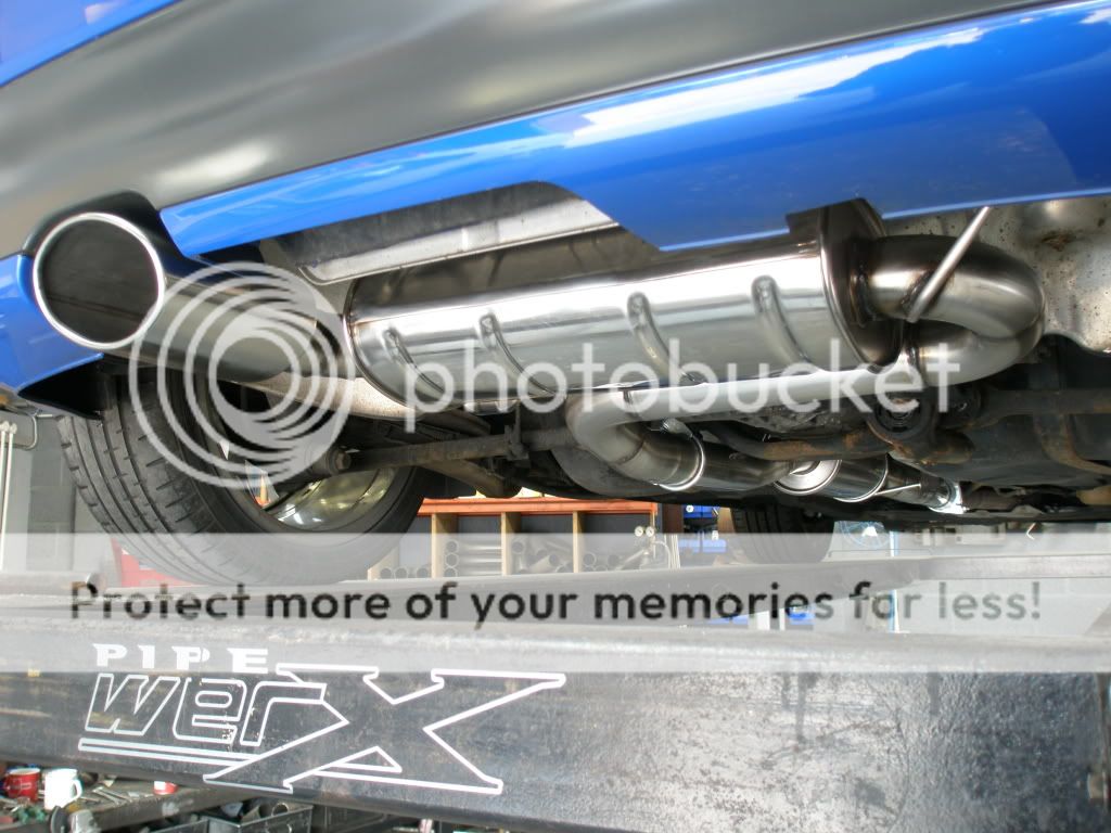
I bought all the bits from the Jetex website in the end...

http://www.jetex.co.uk/website/custom_parts.php?mat=Stainless&dia=3.0+inch

Parts I bought were...

U347663R
SPLIT 76 Silencer box - Oval H=140mm / W=220mm / L=320mm [1 x 3 inch in / 2 x 2.5 inch out]
£103.12
U347663Rbox.jpg

...used for the back box...

U457600R
TURBONETT Silencer box - Round 125mm / L=250mm
£60.96
U457600Rbox.jpg

...used for the centre box...

U690100R
Stainless Steel M18 Lambda Boss (1.5mm)
£6
u690100r.jpg

...used for the post cat lambda

U015150R
500mm pipe with swaged 2 inch end
£13.46
U015150Rbox.jpg

...used to make the slash cut tailpipes


Plus a flange, length of 3" SS tube, 4 x 90deg 3" bends and some SS rod for the hangers that Bill had already (not sure how much as yet, £120ish?)

...oh and some clamps of course :)

I am planning on fitting a different box on the back as its currently a little too boomy in the car under certain circumstances, but it has quietened down quite a bit now its been on a while.


<tuffty/>
 
Last edited:
Bit of an update...

Still trying to sort the exhaust out as I am not happy with the drone in the car. Fitted a sports CAT now and the noise is much better inside and out but still has a bit of a drone thats really annoying so a bit more work to do there....

Had a few cold start issues and boost seems a little all over the place so set about a mission to check for leaks. I have already tested the boost side of things at over 30psi and no leaks so was happy about that but had a good look over the vacuum system.

All the visible pipes looked fine so looked at the less obvious ones. Removed the funny 'V' shaped pipe at the end of the inlet mani that feeds the PCV system and servo..

20100117_IMG00031-20100117-1811.jpg


Brilliant!!!

So based on that I looked at all the pipework under the inlet mani and found splits in the plastic hard tubing and another rubber 'L' shaped pipe that comes from the bottom of the mani to the air pump valve...

20100117_IMG00029-20100117-1810.jpg


I ended up removing most of this and re-plumbed what was left.... servo is now directly connected to the inlet mani where the funny 'V' shaped pipe was (using an appropriate one way valve) and replaced the pipe coming from the bottom of the mani to the air pump valve.

I plan to tidy this up and remove whatever is not needed when I have a bit more time. Here is what I ended up removing...
20100117_IMG00028-20100117-1810.jpg


Off the back of this the engine will sit happily at 1.6bar and feels much smoother under acceleration... result!!! ****** VAG and is EU/emissions pipework nonsense!!!

Seeing as I was on a roll, I tried a manual boost controller to see if could get the boost back up to 1.8bar or so... a quick run later showed the boost peaking at nearly 2bar but settling back to 1.6bar with the MBC wound fully open... something wasn't right...

Bill then suggested adjusting the preload of the actuator... My actuator has gone a bit softer since it was fitted which is not a major problem but Bill felt that the wastgate may well be being blown open due to exhaust pressure and because I have a relatively small hotside.... its got to go somewhere!!!

I removed the actuator and adjusted the arm a tad... put it back on and it hit 1.8bar and held...

Getting somewhere at last, EGT's seem to be happy at 950 degrees on full chat and the car feels much stronger through the gears.

Next tweak on the cards is to change my 007P DV to this...

FMDVSUPR.jpg


This is the same DV Bill runs on his car, it has 40mm inlet/outlet ports versus the 25mm ones of the 007P so hoping this will dump my 1.8bar of boost a little better :)

In the meantime I will be doing some logging runs so that I can get the mapping finished, hoping that I have finally got rid of my gremlins this time as its been a right old run around chasing our tails with all sorts of issues mostly vacuum related...

If I have learned anything from this its that you can never underestimate how crap the VAG vacuum pipe system is and that it should be one of the first places you look if you think you have any performance/running probs with your car...

Here endeth the lesson ;P

<tuffty/>
 
  • Like
Reactions: hydro s3
I was looking at all those hoses today when I was fitting my new hose for the frp. Can most of it be scrapped and simplified?

All the hoses tend to look fine until you actually take them off and give them a good old squeeze an fin they've perrished!
 
  • Like
Reactions: S3Lol
I have left the funny 3 way valve thing connected to the mani/PCV so it still creates the right vacuum to operate the crankcase breather system but replace the 'L' shaped pipe with a bit of silicon vacuum hose and blocked off the bit that returned back to the servo pipe as I pick the servo vac pipe direct from the mani now. I'll try and take some more pics tomorrow to show what I did.

Still got a bit of work to do to tidy it up plus replace a soft but not yet split pipe thats perished from oil...

PITA really but tbh, most of it can go... its all to do with emissions.

<tuffty/>
 
A few more pics of your work would be great. Yesterday I was giving all the pipes in my engine bay a quick one over and some of them look so faded and tired. I'm planning to gradually replace as much as I can since Ive found out how much impact one tiny little hole can have!

If I was to simplify the emisions hosing do you think i'll run into trouble come MOT time?
 
If I was to simplify the emisions hosing do you think i'll run into trouble come MOT time?

Nope

Its not emissions as in MOT, but type approval emissions that vag had to do when they made the car
no effect on mot emissions from these changes, just improved reliability
 
Nope

Its not emissions as in MOT, but type approval emissions that vag had to do when they made the car
no effect on mot emissions from these changes, just improved reliability

Thanks for explaining Bill.

Paul if you could get some pics up of your handy work when your finished, or even better a quick guide I'm sure there will be a few of us that will be very grateful.

By the way this must have been a good weight saving exercise too looking at the amount of junk you ripped out :o.k:

Keep up the good work
 
I replaced that v pipe on the side of the inlet manifold too. One available from Forge.
 
I replaced that v pipe on the side of the inlet manifold too. One available from Forge.

I ditched it althogether... just got the servo vacuum pipe + check valve out of that, ditched the pipework attached to it too... just a vacuum for PCV...

<tuffty/>
 
Nice work tuffy!
Where is the L shaped pipe located, on top of the oil filter bracket? How do you work there? There is almost no room for repairs.

Can descripe more about the actuator ajustments. Again almost no room around the turbo, how do you do it?
 
Last edited:
Nice work tuffy!
Where is the L shaped pipe located, on top of the oil filter bracket? How do you work there? There is almost no room for repairs.

The 'L' shaped pipe comes off the bottom of the inlet mani and is positioned more or less in the middle. It is tight but you will need to remove the little plastic trim panel and unbolt the metal plate (unplug the EGT sensor plug if you have one) from the mani taking extreme care not to break the dipstick tube unless you have a new one to hand... if this has never been off your car I would advise going to Audi and buying a new dipstick and tube as they are only a couple of quid each as it goes brittle and will break.

Once the plate, dipstick tube (just pulls off) is out of the way you will have much more room to play.


Can descripe more about the actuator ajustments. Again almost no room around the turbo, how do you do it?

I would but its not recommended you do this unless you

A) know what you are actually doing...
3) realise the consequences of doing this...
z) know what you are actually doing...

My build is very much custom even to the point that the turbo required a little assembly. There is no reason to adjust the actuator preload on K03's and K04's as they will all be set at the factory... Mine wasn't... I also have a 1bar actuator (unlike the OEM turbo's 0.5bar). I adjusted the preload while building the turbo and fitting it to the engine, obviously it wasn't enough as I am running high boost so I removed the actuator (not as difficult as it sounds) and wound the end in a tad. Re-fitted and all is good...

Doing this without knowing what you are doing could cause your turbo to overboost and the N75 will be unable to control it as it should. This.... is bad!!!!

<tuffty/>
 
Tnx, i will have a look. Already replaced the dipstick tube.

I will leave the actuator as it is. Big tanks for the explanation!
 
Small update...

I have a couple of weeks off coming up as I have been busy work wise so hopefully I will have most of the next round of tweaks and stuff done then... As a taster, here are a few bits I have got ready...

I have finally mounted the Liquid gauge in the drivers vent..

20100203_IMG_3976.jpg


...all thats left to do is wire in a bit of CAT 5 network cable to a switch to enable me to switch the K-Line on the diag socket so that I can switch between using VAGCOM through the socket or the Liquid gauge. As yo can see the vent mount isn't the best fit but does look better than that in the flesh. I may at some point spend a bit of time with it and make if fit better..

With the Liquid fitted in the vent I had to move the boost gauge. Inspired by s3_kev's boost gauge antics (http://www.audi-sport.net/vb/showthread.php?55649-A-pillar-gauges-finished) I got myself a Stack 2bar gauge and had a go...

Only using a single pod as I only wanted the boost gauge there so got a pillar pod from ebay...
20100125_pillar_pod01.jpg


Needed some trimming so sorted that out and sprayed it matt black... I have some black speaker grille cloth which is close to the interior of my car so I will attempt to retrim the pod in that...
20100125_IMG_3956.jpg


I didn't paint the back of my gauge like Kev did but sourced some of the red film used in disco lights...
20100204_IMG00046-20100204-1300.jpg


20100204_IMG00045-20100204-1259.jpg


...I threw it all in the car to make sure it was working ok and took a (crappy) pic of it all lit up
20100204_IMG_3983.jpg


...looking good so that will get finished off when I am off..

Another thing I am doing is changing the DV from a 007P to a Forge Super Size...

20100124_IMG00036-20100124-1335.jpg


A bit of de-blinging later....
20100202_IMG_3971.jpg


Plan is to create a 'cold side' style tap out of the hose going to the throttle body and the DV will sit under the TIP... I will sort out the build pics of that when I do it for a later post.

Last thing to look at will be the exhaust. I am not happy at how much drone my current setup as... its a shame as it sounds fantastic under boost when I go for it but as I drive much more sensibly than that on public roads I am going to have to tone it down a bit... to do that I am getting a chambered box from magna flow which should make it a lot quieter and not hurt the flow that much. The layout will look a bit like this 30 second photoshop hack...
S3-exhaust-01.jpg


...and I plan to get hold of a twin 3" slash cut tailpipe...

One last thing, I should also be geting my final map which will include a fix for the EGT issue and an increase in boost to 1.8bar... then off to the dyno ;P

<tuffty/>
 
Oh yes Tuffty, that liquid gauge looks THE BOOBIES! Nursing a semi....

What are your thoughts on it having been using it?
 
Oh yes Tuffty, that liquid gauge looks THE BOOBIES! Nursing a semi....

What are your thoughts on it having been using it?

Its a brilliant bit of kit for what its designed to do... graphical representation of logging blocks that give you loads of info about whats happening with your engine plus basic fault code finding (engine management codes only from what I understand) and some fun bits like 0-60 timing and dyno plots...

If you like gadgets its pretty damn good... I tend to have it on the custom multi gauge Jim set up for me that shows IAT's, coolant temp, EGT's and AFR.

Boost gauge calibration using the new 'AGU' method is still a bit wiggy for me as its close to my Stack boost gauge reading but not close enough... now thats no reflection on the Liquid but prob more to do with the setup of my car. It may be something that can be sorted once I go RS4 MAF and open induction (with an OEM twist of course) as I have pretty much maxed out the flow capacity of the S3 MAF housing at the moment.

It is not a replacement for VAGCOM though and isn't sold as such but it will give you most of the info you need to help you in diagnosing any problem you may have engine wise (I am going to suggest getting a readout for block 032 as thats really useful to have in there as well) and it looks really cool too...

I prefer the TT fitment of center vent and might revisit this on mine. I had it in the center vent for a while before fitting in the drivers vent and find its easier to read in the center.

If I had the choice of getting either a full copy of VAGCOM or the Liquid, I would get VAGCOM... it suits my requirements better than Liquid... however... If I had easy access to VAGCOM then just buy the Liquid because its does most of what people will want in providing comprehensive info from the ECU and its very very cool.....

<tuffty/>
 
Paul i think you may need some sort of scooby vent cut into your bonnet to get that dv inside, its huuugggeee lol
 
Paul i think you may need some sort of scooby vent cut into your bonnet to get that dv inside, its huuugggeee lol

not very OEM though is it ;P

...but then neither is that DV lol...

I have a special place for it where it will be pretty much out of view so all good...

<tuffty/>
 
Good lord, this is certainly a project and half. Very good to see an OEM looking engine bay, to house the new monster power :) If my S3 was my second car and I could take it off the road, some of your mods would be right up my street!

Brakes are still a serious consideration.
 
Found a bit of time today to finally fit the boost gauge pod and wire up the Liquid so that I can still use my OBD port socket for VAGCOM without having to unplug the Liquid...

First the Liquid... Bought 2 switches from Maplins... the rocker is so that I can switch the K-Line between the socket and the Liquid and a locking push button switch so I can turn the power to the liquid on/off if I needed too. I cut a length of CAT 5 network cable as the Liquid uses a CAT 5 plug and socket for a connection...
20100212_IMG_3988.jpg


Decided that I wanted the switches out of the way where they couldn't be seen and where I wouldn't knock them accidentally so fitted them at the back of the cubby hole under the steering wheel where the service books etc go... access can be gained through the holes under the cubby hole...
20100212_IMG_3991.jpg

20100212_IMG_3992.jpg


Wired up the OBD socket so that it would power the Liquid and cut the K-Line so it can be switched...
20100213_IMG_3994.jpg

20100213_IMG_3995.jpg


Plugged it all together and all works just fine...
20100213_IMG_3997.jpg


Next I set to work on the piller pod. I was going to trim it in a similar fabric to the interior but the 2 different bits I ordered where still no close match so I painted it in a flat black that looks rather like the rubber texture of some of the dash elements in the car...

To fix it on the A piller trim I drilled and countersunk some holes and screwed in self tappers. I then filled the screws over with plastic filler, sanded and painted. I applied hot glue to the screws on the other side to hold them in a bit better...
20100213_IMG_3999.jpg

20100213_IMG_4000.jpg

20100213_IMG_4002.jpg


Fitted it all back in the car and doesn't look too bad :)
Daylight shot of the normal white dials...
20100213_IMG_4003.jpg


Darker shot showing the red back lit dials with white needles...
20100213_IMG_4005.jpg


And finally a couple of close ups...
20100213_IMG_4006.jpg

20100213_IMG_4007.jpg


All in all a good days work and pleased with the results....

<tuffty/>
 
  • Like
Reactions: AdzA3AGU
I actually think that looks better than it would have done covered in fabric, I'm definitely going to be doing this :)

Oh by the way how the hell did you get you light switch out so far? I cant even get it 2" out because the wires are so tight.
 
...Oh by the way how the hell did you get you light switch out so far? I cant even get it 2" out because the wires are so tight.

I removed the lower part of the dash mate... was driving around for a week or so with the light switch dangling...

<tuffty/>
 
Looking good paul! I'm liking how your spraying everything black, stealth!

I hope the exhaust sounds better and droons less once you've put the rear box side ways, i had mine made that way and i was surprised how quiet it is inside the car, i'm getting the downpipe and cat soon so i'll see how it changes.

I've put a picture up of how my was done, the centre part is a little different to yours though
P4170524.jpg
 
Looks exactly what I need mate... what size is the back box? I have one in mind.... its a magna flow turbo XL chambered box but they are out of stock of the 3" ones until the beginning of March so will have to put up wiht the noise until then :(

<tuffty/>
 
Got the piller pod from ebay Neil...

http://stores.shop.ebay.co.uk/cs-automods

Linked to the shop rather than the item so that the link has a chance of surviving longer than a week :)

Should be noted that I did do a bit of trimming to get it to follow the contours of the trim panel and I also used a hot air gun to help with the forming of it too...

<tuffty/>
 
Last edited:
Cool, thanks mate... looks just like my planned adjustment once the boxes are back in stock :)

<tuffty/>
 
how do you get the A pillar trim off? and also is the easiest way to run the pipe for boost gauge through the drivers side? have you any pics of this part of the install?
 
good job on the gauge mate as expected by you lol
 
If you can Paul it would be awesome if you could put a before and after soundclip up when it's done :)

Already have a vid of the current setup posted further up somewhere but I will post that and the new one once I have done the work :)

how do you get the A pillar trim off? and also is the easiest way to run the pipe for boost gauge through the drivers side? have you any pics of this part of the install?

I don't have any pics of this no... the A piller trim is held on by 3 of those lovely metal clips that generally will break the trim rather than let go of the part of the body they are holding on to but it is as simple as getting something under the trim like a large flat bladed screwdriver at these 3 points and popping the trim up to release it from the the A piller...

As for running the pipe, on my original gauge I used a but of 3mm or 4mm rubber fuel hose through a grommeted hole I made in the plastic cap where all the wiring from the inside of the car comes out of the scuttle. There are only a couple of places to run cables/pipes etc into the interior of the car, one being the grommet by the pollen filter on the passenger side and the other the plastic cover bit... I chose the plastic cover as it was neater to run the pipe in the scuttle than under the dash.

good job on the gauge mate as expected by you lol

Thanks mate, all thanks to your original post though so credit where credits due..

<tuffty/>
 
As for running the pipe, on my original gauge I used a but of 3mm or 4mm rubber fuel hose through a grommeted hole I made in the plastic cap where all the wiring from the inside of the car comes out of the scuttle. There are only a couple of places to run cables/pipes etc into the interior of the car, one being the grommet by the pollen filter on the passenger side and the other the plastic cover bit... I chose the plastic cover as it was neater to run the pipe in the scuttle than under the dash

Do you have to remove the wipers to lift the scuttle panel to get the pipe for a boost gauge into the car? only had a quick look today and dont want to be taking stuff off unless I have to :)
 
Yarp, wiper arms need to come off really... not difficult to do tbh :)

<tuffty/>
 

Similar threads

Replies
5
Views
1K
Replies
1
Views
1K
D
Replies
0
Views
702
Deleted member 65282
D