

My A6 3.0TDi Avant bit of a rebuild and repair thread.
- Thread starter B5NUT
- Start date
You are using an out of date browser. It may not display this or other websites correctly.
You should upgrade or use an alternative browser.
You should upgrade or use an alternative browser.
Is this just removal of CP from central electric? if so then it's very simple fault guided diagnostic, that all techs will be trained on. I've used Audi's systems with no training and it's so simple to use.. The problem comes when you are fitting modules that don't belong to that year of car MMI 3GP retrofit for example.
As I said before another option is to flash the central electrics module which is what i did, avoiding CP issues.
As I said before another option is to flash the central electrics module which is what i did, avoiding CP issues.
Irnman
Registered User
- Joined
- Mar 5, 2016
- Messages
- 40
- Reaction score
- 0
- Points
- 6
Well its the central elecs unit out of a slightly later year of car, but still in that same model (its the revision K module - same part number but with K at the end). I didnt think it would be easy or cheap to get hold of the software to flash the old module and given i am new to this - believe it or not, i thought this would have been more straight forward.....i may have been wrong.
That's fine it's still classed as module 09 under diagnostics. I have the software to update the firmware on the module, but I'm based in Darlington. The VCP software is not cheap it's 244euro. You could try and used the old versions of VAS that are available on ebay, but make sure you get one with the OKi chip which allows flashing of modules.
Irnman
Registered User
- Joined
- Mar 5, 2016
- Messages
- 40
- Reaction score
- 0
- Points
- 6
Lol, if i dont get this sorted soon, we are heading to blackpool in 4 weeks, so i might just take a day trip over lol! Would the pins etc that i move to accommodate the night lights and for this revison K module still be in same place? I wouldnt have to backtrack? What happens with CP if i put the old module back in - does it just pick up where it left off - i.e. no cp?
There are pin differences for the LED headlights & side indicators (FL has them in the wing mirrors) but all the other pins are the same between the two modules. I still have working side indicators with LED headlights coded.
spyderboyant
Registered User
- Joined
- Jul 24, 2015
- Messages
- 18
- Reaction score
- 2
- Points
- 3
Hi spyderboyant,
where did you find the flash file "4L0910468A__0071"? I unzipped many audi_flash zips... always "4L0910468A__0060" is the latest.
Send me a PM and I can email it to you.... I got it from vag-tech.
spyderboyant
Registered User
- Joined
- Jul 24, 2015
- Messages
- 18
- Reaction score
- 2
- Points
- 3
Also, I think from my testing with 26pin CAN gateway, you can get most things controlled by the MMI but not all. I'll post my final configuration when I install ACC,.
spyderboyant
Registered User
- Joined
- Jul 24, 2015
- Messages
- 18
- Reaction score
- 2
- Points
- 3
There are pin differences for the LED headlights & side indicators (FL has them in the wing mirrors) but all the other pins are the same between the two modules. I still have working side indicators with LED headlights coded.
@B5NUT, do your LED lights dim when your main xenon head lights come on? On another site, I have seen the coding stated as "0023121" if the convenience module 09 is replaced with an FL version but to use 0015121 if using adapters/resistors.
I've upgraded my convenience model but can only get everything to work with the original 0015121 coding. That is everything besides dining Drls when the bixenons are on
I don't think they do, but I have not checked. I cannot remember what my coding is would have to check the car.
Irnman
Registered User
- Joined
- Mar 5, 2016
- Messages
- 40
- Reaction score
- 0
- Points
- 6
Well,
I done the wiring under the steering wheel (central elecs), today, was hoping i would get led drls coming on....i didnt! Tried several different codings, but i think i should be 0006121. I did try 0009121 which is drl with led drl and afs, but i dont think my car has afs so it wouldnt take this code, kept saying code was out of range.
I think my next move is to check the plugs going into the headlight units are using correct pins - i have a feeling that perhaps the fleabay store i bought them from were only getting them to convert hallogen to xenon (without led drl). So i might need to move some pins on this side, as i am sure my wiring is ok inside the car. Do you know what the hallogen unit on the inside of the headlights is for - as this doesnt light up either. My headlight is giving me low beam xenon and my full beam / flasher is giving me high beam via the xenon switch. Is this correct, or do i have an error somewhere?
Well,
I done the wiring under the steering wheel (central elecs), today, was hoping i would get led drls coming on....i didnt! Tried several different codings, but i think i should be 0006121. I did try 0009121 which is drl with led drl and afs, but i dont think my car has afs so it wouldnt take this code, kept saying code was out of range.
I think my next move is to check the plugs going into the headlight units are using correct pins - i have a feeling that perhaps the fleabay store i bought them from were only getting them to convert hallogen to xenon (without led drl). So i might need to move some pins on this side, as i am sure my wiring is ok inside the car. Do you know what the hallogen unit on the inside of the headlights is for - as this doesnt light up either. My headlight is giving me low beam xenon and my full beam / flasher is giving me high beam via the xenon switch. Is this correct, or do i have an error somewhere?
On FL cars with bi xenons such as mine the headlight unit (halogen) on the inside is only used for flashing etc it does not come on for either dipped or main beam functions which is wrong in my opinion as the light output is better with it on. Its a pity it cant be rewired to work!!
Hope that helps
Irnman
Registered User
- Joined
- Mar 5, 2016
- Messages
- 40
- Reaction score
- 0
- Points
- 6
This does help, thanks you, as i did think if it might wear out the bixenon switch if that was also used as the flash as well! So from that i must assume that my thoughts on my ebay wiring harness are correct and that it isnt going to the correct pins for the facelift light (possibly just wired from conversion from prefacelift hallogen to prefacelift xenon - although a am not to impressed, as i did ask the seller if it was fit for this purpose prior to purchase).
Does anyone by any chance have a pin layout of the connector at the back of a facelift headlight - if i can get this, i am sure i can realign the connector properly with the aid of a voltmeter.
Many thanks to the forum for their help.
Oh, and car is now booked in to another Audi dealer to attempt to have cp lifted. Glasgow Audi refused to do it.
Slackworth
Registered User
If it's a main dealer then you should be fine. ") they just need to do it manually rather than via SVM or it'll fail miserably. As B5NUT says, they should know what they're doing though!!!
they just need to do it manually rather than via SVM or it'll fail miserably. As B5NUT says, they should know what they're doing though!!!
An Indy can have a genuine version of VAS/ODIS along with matching hardware but doesn't mean they are paying for the GeKo license which is a separate license with a rather whopping cost!
they just need to do it manually rather than via SVM or it'll fail miserably. As B5NUT says, they should know what they're doing though!!!An Indy can have a genuine version of VAS/ODIS along with matching hardware but doesn't mean they are paying for the GeKo license which is a separate license with a rather whopping cost!
Irnman
Registered User
- Joined
- Mar 5, 2016
- Messages
- 40
- Reaction score
- 0
- Points
- 6
I will mention when i go along to do it manually (as i just want this done now without any further complications)!
If anyone has a pin layout for a facelift headlight so i can finalise my wiring i would be grateful. Failing that, does anyone know which pins i can supply 12 to in order to test the led as working (although the seller did assure me he had tested before removing from car).
If anyone has a pin layout for a facelift headlight so i can finalise my wiring i would be grateful. Failing that, does anyone know which pins i can supply 12 to in order to test the led as working (although the seller did assure me he had tested before removing from car).
Irnman
Registered User
- Joined
- Mar 5, 2016
- Messages
- 40
- Reaction score
- 0
- Points
- 6
I appreciate everyones help and input - my knowledge going into this project was limited, but by the time its done, i reckon ill have a bit better understanding of things like vcds and component protection etc.
I just want to try and get things finished - spent my breaks and lunchtime and this evening googling trying to find a pin layout for the headlights lol (unsuccessfully), will go at it again tomorrow.
I just want to try and get things finished - spent my breaks and lunchtime and this evening googling trying to find a pin layout for the headlights lol (unsuccessfully), will go at it again tomorrow.
javo
Registered User
- Joined
- Jan 31, 2016
- Messages
- 6
- Reaction score
- 0
- Points
- 1
@B5NUT, do your LED lights dim when your main xenon head lights come on? On another site, I have seen the coding stated as "0023121" if the convenience module 09 is replaced with an FL version but to use 0015121 if using adapters/resistors.
I've upgraded my convenience model but can only get everything to work with the original 0015121 coding. That is everything besides dining Drls when the bixenons are on
Probably should swap wires pin 10 and 12 on headlight connector when using pre-FL wiring with FL headlights (for dimming DRLs when xenons are on.)
Attachments


Irnman
Registered User
- Joined
- Mar 5, 2016
- Messages
- 40
- Reaction score
- 0
- Points
- 6
Thanks javo, and i hope i dont get shot down for this, but i dont really understand what i am looking at.....i thought a pin diagram would just be a basic diagram with the 14 pins and an indicator as to what input each pin was expecting. I am guessing this is the sort of diagram an auto electrician would use to trace circuit of each input?
spyderboyant
Registered User
- Joined
- Jul 24, 2015
- Messages
- 18
- Reaction score
- 2
- Points
- 3
I've just figured out the wiring for the FL LED headlights (for a Q7 anyway). When flashing J519 to software N (from K) or replacing with a FL module, the drivers in the module change function/pins. So in my instance, T32b/3 and T32b/14 change from the turn indicators in the side external mirrors to the wires that drive the LED DRLs. This is because in the Q7 FL, the mirror turn indicators are driven by the door electronics and the pins that used to be used for the side mirror turn indicators are now used to drive the LEDs! From a wiring perspective, the wires that were going to t32b/4 & 15 (marked in older wiring diagrams as side light left/right) need to move into T32b/3 and T32b/14 as these drive the LEDs. To achieve this, you need to remove the current wires from these pins as they are for the side mirror turn indicators.
Now, the old side mirror indicator wires are not connected to anything. To get the side mirrors to now work, you need to solder them to the front left (T12b/10) and front right (T12b/9) wires which are the wires for the front bumper LED turn indicators.
Finally, to make it all work, you need to change the coding from the old LED coding of 0015121 to either:
0032121 for Bi-xenon or
0033121 for Adaptive Bi-Xenon
Now everything should work with dimming DRLs and working side mirror LED turn indicators.
Now I can remove the VNS media LED facelift adapters which I initially installed with the LED coding of 0015121 but didn't provide me with dimming (as I didn't soldered the wires as discussed on other forums across pins within the J519).
I hope this helps someone as it has done my head in trying to get them to work correctly. I really struggled with the new wiring and finding out that with the FL, the side mirror indicators have moved to the door controllers from J519.

I've just figured out the wiring for the FL LED headlights (for a Q7 anyway). When flashing J519 to software N (from K) or replacing with a FL module, the drivers in the module change function/pins. So in my instance, T32b/3 and T32b/14 change from the turn indicators in the side external mirrors to the wires that drive the LED DRLs. This is because in the Q7 FL, the mirror turn indicators are driven by the door electronics and the pins that used to be used for the side mirror turn indicators are now used to drive the LEDs! From a wiring perspective, the wires that were going to t32b/4 & 15 (marked in older wiring diagrams as side light left/right) need to move into T32b/3 and T32b/14 as these drive the LEDs. To achieve this, you need to remove the current wires from these pins as they are for the side mirror turn indicators.
Now, the old side mirror indicator wires are not connected to anything. To get the side mirrors to now work, you need to solder them to the front left (T12b/10) and front right (T12b/9) wires which are the wires for the front bumper LED turn indicators.
Finally, to make it all work, you need to change the coding from the old LED coding of 0015121 to either:
0032121 for Bi-xenon or
0033121 for Adaptive Bi-Xenon
Now everything should work with dimming DRLs and working side mirror LED turn indicators.
Now I can remove the VNS media LED facelift adapters which I initially installed with the LED coding of 0015121 but didn't provide me with dimming (as I didn't soldered the wires as discussed on other forums across pins within the J519).
I hope this helps someone as it has done my head in trying to get them to work correctly. I really struggled with the new wiring and finding out that with the FL, the side mirror indicators have moved to the door controllers from J519.
Now that you have sorted it, it would be good if someone could advise on a way to get the flasher (inner) lights on a bi xenon headlight to come on with main beam!!

spyderboyant
Registered User
- Joined
- Jul 24, 2015
- Messages
- 18
- Reaction score
- 2
- Points
- 3
Do you mean when using the high beam flasher the high beam stays on? If so, didn't someone mention that a facelift turn stalk/indictator is required to make it behave as normal?
Do you mean when using the high beam flasher the high beam stays on? If so, didn't someone mention that a facelift turn stalk/indictator is required to make it behave as normal?
I want the flasher (inner) lights to stay on rather than just flash ideally. Mine is a facelift car.
Irnman
Registered User
- Joined
- Mar 5, 2016
- Messages
- 40
- Reaction score
- 0
- Points
- 6
Aarrrggghhhh.......right guys...please help! I am quickly approaching my wits end with this retofit. I took the car to Ayr Audi today for them to try and lift the component protection, and they ran into same issue as the specialist. The guy was really good and he tried various things, but it kept coming back with this same message (see pics attached). Which when i run through google's crude translator, gives us this messsge:
Error message in DISS as technical inquiry (Theme anti-theft alarms immobiliser) formulate.
Without error and User ID no processing in the Export/SEAT/Skoda competent public product care hereby inform.
So.....anyone know what this means - is it saying there is something wrong with the cars I immobiliser, or is it saying that the new central elecs module is from a reported stolen car or is it just saying that its refussing to lift the component protection, and if so.....why?
As always, help appreciated.
Attachments
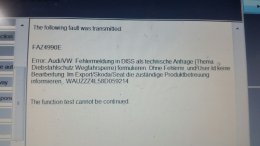
Yes I know what that error code means, the part has come from a stolen car that has been reported to Audi. You will never be able to remove CP from that module, as all the modules are black listed by Audi's gecko database.
Depending on where you got the part try and get your money back or report to the police.
Depending on where you got the part try and get your money back or report to the police.
Irnman
Registered User
- Joined
- Mar 5, 2016
- Messages
- 40
- Reaction score
- 0
- Points
- 6
Thanks for letting me know...believe it or not, i am actually quite glad to hear that...as at least i now know why it wont release cp. I am not obviously glad for the poor soul who's car has been stolen and chopped up! I bought it on ebay and its past the 41days (or thereabout) where you can raise a dispute, but i think i will get it out of the car and report it to the police just to keep myself right.
Thanks for the info.
Hopefully the module that arrives tomorrow is clean lol.
Thanks for the info.
Hopefully the module that arrives tomorrow is clean lol.
spyderboyant
Registered User
- Joined
- Jul 24, 2015
- Messages
- 18
- Reaction score
- 2
- Points
- 3
Hey Ajax,Here is the list of Extended CAN gateways you can use:
26-pin:
4L0 907 468 A, SW: 4L0 910 468 A
4L0 907 468 C, SW: 4L0 910 468 A
20-pin: (you will need this if you want to go to 3G+)
4F0 907 468 G, SW: 4F0 907 468 G
4F0 907 468 G, SW: 4F0 907 468 L
4F0 907 468 G, SW: 4F0 907 468 N
4F0 907 468 G, SW: 4F0 907 468 Q
4F0 907 468 G, SW: 4F0 907 468 S
You will need at least N revision to go to 3G+. Any previous index of 20-pin gateway can be updated to N by software.
AJAX
In relation to the CAN gateways, do you know what the limitations of using the 26-pin vs 20 pin for the 3G+ are?
The reason I ask is that I have the 26-pin HW:4L0 907 468 C SW: 4L0 910 468 A - flashed to 0071 with a 3G+ head unit and everything works great EXCEPT access to the instrument cluster. What this means is I cannot see the on-board computer and more importantly , cannot set the clock in the cluster or get time on the MMI clock (mine shows -
. This means simple things like using SAT Nav doesn't show the expected time to a destination but the actually duration time of the trip. So when it comes to the time in the instrument cluster , I need to set it via the adaption channels in the cluster with VCDS (I'm in Australia so no radio clock).I can control all other available controllers (central for DRL lights, HVAC for AC, memory seats) by setting in the engineering menu of the MMI 3G+ the canbusassignment to [Clamp 15]. No other can bus assignments work as per other forums notes where different CAN bus assignments are used. This makes me think that this is because of this older gateway and to get full functionality I need to get the latest fw revision with the 20pin gateway.
In another forum someone mention version 0080 for the 26 pin controller. For the life of me I cannot find any reference to it and if it exists would love to flash my gateway to see whether it brings the gateway up to the functionality of the 20pin version.
As I have a 26-pin gateway I am not overly keen on moving to the 20pin version as (a) I will need to get CP removed, (B) will need to play with the Battery Energy Management (BEM) [run new wires] so that I remove the BEM errors. As an experiment I might just put in the 20pin CAN gateway I have and hopefully see if I'm lucky whether I can use the other CAN buses via the canbusassignment when CP is invoked. If I can change the CANBUSASSIGNMENTS and get this to work then we can categorically state that not all functionality can be achieved between an MMI3G+ and a 26-pin CAN gateway with 0071 software.
thanks
A
What condition were your slider pins in as when you get uneven wear quite often it can be because they are jamming up.
sweet. ! mine are grown up now. my lads just bought an A3 aswell. knew he would after bash in my a4 quattro. lol.. cherish these times mate. 1 min their climbing all over you and before you know it their gone.Very well, I've been meaning to update this thread with the other things I've done but the little one is taking so much time up it's unbelievable, I've go no idea how such a small baby can take up so much time, and the term "sleeping like a baby" is total BS, I've heard of the Duracell Bunny, but I've got the Duracell Baby she goes on, and on and on.....
Still the best thing I've ever done

have you any idea why my handbrake wont release after changing rear pads. 02 A4 with windback piston.. worked ok after changing 1 side. then not releasing after other side done.If you don't mind your car off the road for a few days then a cheap option is to get your gateway upgraded by kufatec. http://www.kufatec.de/shop/en/update-service/can-gateway-software-update-audi-vw
Irnman
Registered User
- Joined
- Mar 5, 2016
- Messages
- 40
- Reaction score
- 0
- Points
- 6
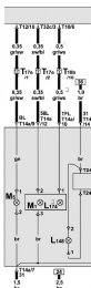
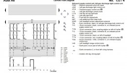
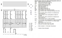
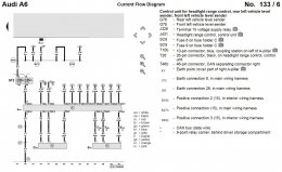
Hi Javo,possible pinout for FL Bixenon headlight without cornering light.
Thanks for the wiring diagrams, these dud make sense to my mechanic, however we were unsuccessful at testing the wires coming from the car (he mentioned something about the wires being fed a duty cycle and if they didn't detect a proper circuit they wouldn't provide power. Therefore I am wondering do you also have a wiring diagram for my current hallogen headlight setup (2005 A6 Avant), so I can compare pin locations and feeds?
Tried googling, without success - do you have a cd or something with these diagrams etc?
Thanks

spyderboyant
Registered User
- Joined
- Jul 24, 2015
- Messages
- 18
- Reaction score
- 2
- Points
- 3
You need to change the voltage regulator on the alternator, but there are different versions depending on if you have a Valeo, or Bosch alternator. You can tell a FL version as it only has a single pin on the voltage regulator where the old version had two. You then need to disconnect the plug going to the current voltage regulator. One of the wires (don't remember which) goes to the new battery monitor module, then a new wire is run from that module to the can gateway. That will clear all your faults, and should clear up heated seats etc.
Here is a picture of the new battery monitor

Part number of that cable was 8X0915181
Just thought I would add some additional information around the need to replace the voltage regulator in the alternator (or complete alternator - replacement with updated Voltage Regulator) and the J644 Battery Monitoring control unit with a new battery monitor cable J367 (in my case for a Q7: 8K0915181D).
The reason for this is that from 2009 onwards in the Q7 the J644 was replaced with the above solution which utilises a LIN bus to pin 2 on the 20 PIN CAN gateway. The J644 Battery Monitoring control unit has a 14 pin connector where one of the pins (8) goes to the older alternator and communicates with the Voltage Regulator on the alternator via a BSI (Bit-synchronous interface) on its PIn 1. J644 then communicates with what it needs to communicate charging and battery status with over its Convenience CAN connection.
The addition of the 20 PIN CAN gateway lines up with the introduction of the MMI3G and is the reason why my 26 pin gateway with version 0071 of firmware is not 100% compatible with my MMI3G+ and hence my need to replace it :-(
In relation to the Q7 alternators, there were originally 3 with the first 2007 cars. The third alternator, Hitachi is a Water Cooled Alternator that was installed in the 4.2L V8 engine version. With the newer TDI motors and 3.6Ltr FSI they introduced Bosch alternators with 190A output. Either a 180A or 190A should work.
Anyway, to perform this upgrade all you need to do is make sure that you get a LIN BUS compatible Voltage Regulator! Unfortunately, as mentioned by B5NUT and Ajax, you need to actually remove your Alternator if you only want to replace the Voltage Regulator so depending on the age of your car you might as well replace the whole alternator with a new VR (if you can get one for a good price - not directly from Audi then
)From a wiring perspective, you will need to disconnect the 14 pin connector from the old J644 and install the new battery monitor cable J367. You will need to take the wire/pin 8 from J644 connector and put it into pin 1 of J367 2 pin connector (T2az). Pin 2 on J367 needs to be run to pin 2 on the 20 pin CAN gateway. An option here to minimise running cables is to re-utilise one of the now no longer needed Convenience CAN wires from J644 Pins 9 & 10 (remove from CAN block T46a and solder a wire extension and run into pin 2 of the CAN gateway.
I hope this may help others going down the 3G+ path in either an 4F or 4L
Attachments
Irnman
Registered User
- Joined
- Mar 5, 2016
- Messages
- 40
- Reaction score
- 0
- Points
- 6
No worries Javo - could you just confirm for me though - those diagrams you gave me are for Facelift lights? I seen a wire going to what is described as a daylight driving light, but my understanding of the new Facelift lights is they need 2 wires supplying power in order to light up? I may be wrong....can you just clarify.Irnman, sorry I haven't wiring for halogen lights. I retrofitted fl-xenon from MY 2006 xenon to ex A6 4F.
Any advise on this retrofit is appreciated - I am trying all avenues, but most advise is pointing me to go to a place specialising in this, however most are in London. If it were just me, I would probably make the trip, but my wife doesn't keep well and I can't leave her with the kids for that long (it would need to be an overnight thing), as I live in Glasgow. So going to have to do this myself.
javo
Registered User
- Joined
- Jan 31, 2016
- Messages
- 6
- Reaction score
- 0
- Points
- 1
yes, those are for FL lights. Yep, 14(A/B) pins 10&12 needs +12V (and ground to pin 7) for led light up, see pictures. You maybe need 4F0907279 (Module 09 - Central electrics) with software version 4F0910279N for fully functional like led dimming with xenon lights on and turn lights led dimming.
Last edited:
Irnman
Registered User
- Joined
- Mar 5, 2016
- Messages
- 40
- Reaction score
- 0
- Points
- 6
Well guys, was back out at Audi Ayr today following fitting the replacement Central Elecs module at the weekend (2nd one), finger crossed all goes well.......it didn't! Same message appeared! Workshop manager came out and advised that they have tried fitting "used" modules to cars before and Audi doesnt like this, so throws up this error. I am at a bit of a loss, as without getting this lifted, I can't really continue. I don't believe both modules from separate reputable breakers can be stolen and the tech at Audi didn't believe they were either......I again seek your input?