Installing a new circuit into fuse box

Gazthesparky

Member
VCDS Map User
Joined
Dec 28, 2011
Messages
218
Reaction score
18
Points
18
Location
Glasgow
Hi guys

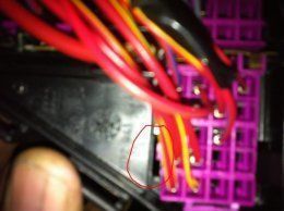
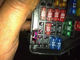
I'm in the process of doing a couple of mods to my a4 B7 cab. These require installing and wiring the components back to the fuse box. I'm retrofitting an auto dim mirror which has its own space in the fuse box so to keep it all OEM I want to use the fuse way. My question is how do the positive wires connect into the fuse box ? Do you have to by the correct terminal crimps and then slide them into the fuse box in the correct positions ? Just to clarify this is to install a fresh circuit and not tap into a excisting circuit

Cheers
 
Yeap 1st make sure the fuse feed is there from the under bonnet supply, if so then you need to grab the repair wires from audi to push into the other fuse side to the mirror, if neither are there, then tbh I always run the correct feed through from under bonnet to the feed side, which usually gives another 6 fuse positions, depending on the bar you need for your car, that way no chance of blowing any circuit it wasnt designed for, gives me peace of mind as I dont need to go back for something I was to lazy to do, plus safety etc, number of reasons.
 
I'm doing the same (adding fuse 18 to the LHS power for xenons), Ive opened the fuse box but cannot add the repair terminal into the empty slot, I know Audis have a simple locking system on all connectors, but I cannot, for the life of me find it on the fuse box, so I can unlock to insert the terminal and then relock it.
Any help or even picture will help.
 
The lock is part of the housing, the pink part slides down/up inside the black housing, look for a little plastic tab that needs pushing aside to allow the 2 to move against eachother, its very minor movement overall.
 
Thanks for getting back to me, is it the ones I've marked in the picture, if so which way do they move ? (the pink ones move...yes ?) IMG 0790
 

Attachments

  • IMG_0789.JPG
    IMG_0789.JPG
    36.3 KB · Views: 531
  • IMG_0792.JPG
    IMG_0792.JPG
    58.3 KB · Views: 560
Last edited:
TBH pics arent great & its late for me, but you should be able to work it out now with that in mind mate, wish I could be of more help, but had a headache most of the day so trying to chill lol.
 
  • Like
Reactions: pistonripper
Thanks for getting back to me, is it the ones I've marked in the picture, if so which way do they move ? (the pink ones move...yes ?)View attachment 9302

As NHN says its hard to tell from the pictures but if you look closely you should be able to work it out.

Down the side there are small tabs stopping the pink cover from sliding. Put a screwdriver in between the black tab and pink cover you should see which way it slides. If this kinda makes silence you slide it agenst the natural way of the tab. Should be easier to see/understand what needs to happen once u have a screw driver in.
 
The lock is part of the housing, the pink part slides down/up inside the black housing, look for a little plastic tab that needs pushing aside to allow the 2 to move against eachother, its very minor movement overall.

I know I’m bringing up a very old thread here but after unlocking the retainer, how do I remove the pin as pulling doesn’t do anything on its own.

Thought I’d put it this thread since it’s already got very useful information.

cheers!
 
You need to use pin removal tools to get them out as they have side metal pieces that have to be pushed back to allow the pin ends to slide out, once out, you can pull the side pieces out again with a Stanley knife, so when they're pushed back in they again are tight in the socket.
 
There's a kit with blue handles from Laser iirc, had mine for years, the ends bend a bit when using but they bend back into shape, it's normal as the genuine vag kit is about £1k.
 
  • Like
Reactions: Arkious

Similar threads