How to: Vent mounted boost gauge for £20

bentwenty

Registered User
Joined
Feb 13, 2014
Messages
345
Reaction score
56
Points
28
Location
Gloucester
Hi, this is how I did the vent mounted boost gauge install for £20. This will work on the A3 8p and S3 8p.
This is a work in progress, so I will update as I finish it. I am posting this now as there has been quite a bit of interest in this mod in a few different threads, so I thought my progress may be useful :)

First of all, credit goes to Mindak, Muzza80 and smurfworth for the idea and help getting the right parts!

Note: to get the nice OEM look, you will need to butcher your original vent with a dremel! If you are uncomfortable with this (like me), you can buy a spare on eBay for a tenner.

You can do this install with the OSIR vent mount, and I in fact bought one. But I decided against fitting it as I don't think it looked that good.
cd19878e6e248800ea6fcc12c1daf448.jpg


You will need the following tools: a dremel, a very small flat head screw driver, a larger Philips head screwdriver, a hot glue gun and a drill with a 6mm bit.

You will only need to buy this 60mm gauge, others might work, but this one definitely will http://pages.ebay.com/link/?nav=item.view&alt=web&id=400568539743
I chose a stepper-motor driven gauge so I don't have to run a vacuum line from the engine bay, this also minimises the possibility for air leaks.

First of all remove your vent from the car, it comes out easily by getting your fingers behind the trim ring and pulling.

Next pop the silver trim ring off the front of the vent using the small screwdriver, make note of its orientation as it is important!
e4646e2c9f1578f0859d6f4c6d52b6f1.jpg


Next remove all the fins by pulling them out with your fingers, they should all come out without damaging them.
c4ee388bb0ea3272a4545dba95ffb10f.jpg

532bf3a7835a42fb272c103d6e037ae7.jpg


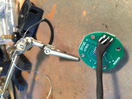
Next disassemble the boost gauge by undoing the screws, and carefully prising back the front trim ring.
3c4fc213795c40a8e32b5db06d8bd7c3.jpg


Now hot glue the front plastic onto the gauge, then glue and bend the front trim ring back on.
72a58b680f113076473246ee76c5f30e.jpg

57e20fe3fafd2c09e3a3eb9451fd638c.jpg


Now the scary part, this re-assembled gauge is still slightly too big for the vent, so you need to crack out the dremel. You will need to do two things; you will need to make the main diameter bigger for the face of the gauge, note that the face is slightly larger than the silver trim ring on the vent, so it has to sit below it.
You will also have to cut a step into the body of the vent to allow for the circuit board. I messed this step up and went too deep. Fortunately the gears still work as I will be using them later :)
ec1073858885b7ae083e6595df05312a.jpg

1970749c118d9d1859c078dd3615019b.jpg
337d1926aa40e8579155de10509b1cf8.jpg


Once that is done, thread the wire though the hole, plug in the gauge and put it in the vent, then clip the silver trim ring in.
a1130de4121fa6ea1afb65099844a3a3.jpg

5c4890fd0f51d83cfad77accaa335741.jpg


I will also be adding a micro-switch that turns off the backlight when the dial is turned off, I will include details on how to do that in the update

This is as far as I have got, I will be installing it next Friday at the same time as an EGR delete and a remap with Darkside Developments. I will update when it is done :)

Hope this helps, and any feedback is welcome!

Ben
 
Last edited:
  • Like
Reactions: 54V4G3, voorhees, Doogie... and 3 others
Book marked for when i do this.

From what i've read, is this a slighty more tedious way of doing it? If you buy the Osir mount, does that not effectively mean you have to do less cutting and trimming etc as for the extra £20 i wouldn't mind that over fiddling about with a dremmel.

Or would you say this was more simple.

Upload details of how to wire it in also when you get around to it!

Cheers
 
You are absolutely correct, this is the more difficult way of doing it. I am doing this was for 3 reasons: it is cheeper (although I do already have the OSIR mount), it will block off the vent in the dash, with the OSIR mount, the vent outlet is left open and will blow a good portion of your hot air into the space behind the dash, and finally it allows me to do the neat little trick with the switch and the lights :)
I will
Certain cover the wiring when I do it :)

PS if anyone wants my OSIR mount PM me and we can work something out :)

Cheers
 
Looks good to me already bud, i do worry that a remap will render the gauge useless though as my tdi mapped to 2.5bar at 175hp
 
Looks good to me already bud, i do worry that a remap will render the gauge useless though as my tdi mapped to 2.5bar at 175hp
Thanks :) I hope not haha. As a precaution, before I ordered the gauge, I spoke the Darkside; on their stage one custom map, most BKDs seem to make about 1.6-17 bar.
 
  • Like
Reactions: smurfworth
ahh i see, i only had a cheaper map on it, thats what you get for quality i suppose.

bet you won't get heaps of blacksmoke from it with one of their maps like i used to either
 
Haha it already smokes like a chimney with just a 2.5" decat so I'm not sure how it will be on the map. Was well within for the MOT smoke test though.
 
Update 1:

I've just finished adding the on/off switch for the gauge backlight. This is not essential to the install, but I'm a sucker for detail, and since the dial around the outside won't be doing anything, I thought it would be worth making use of it...

I used this switch http://pages.ebay.com/link/?nav=item.view&alt=web&id=301294168678
Some hot glue, a dremel, a soldering iron, some solder, some small heat shrink and a hot air gun.

The switch has three contacts labelled C (common), NO (normally open) and NC (normally closed). When the switch is not activated, C is in contact with NC, and when the switch is activated, C is in contact with NO.

The switch can be wired either way, I chose to use the NO contact as the switch fits better in the vent if it is on the open side of the crank. The way I wired it means that the backlight is on when the vent is open.

First you need to make a cutout for the switch using the dremel
c881cc070f6eaddbf055ed3af28c426e.jpg

2d69e7c661feb828f9a2674f1361f4d2.jpg


Next you need to connect up the switch. You need to chop the yellow wire, and solder one end to the C pin and the other to the NO pin, and put some heat shrink on it.
07aa4a068a58483b56a35e0a8aac0885.jpg


With this done, put the switch in the cutout and hot glue it in place, make sure it as at the correct night so that the switch clicks when the crank presses it.
9803a18085d6876c6e11f1498951cfb6.jpg

279c6546aebca99e6ab5ec24eb9b7943.jpg


I hope this is helpful. I am trying to write it with people with little or no experience in mind, I hope it doesn't all insultingly simple!
I will update once I've installed it all on Friday :)
 
Very useful mate, Will be copying this part of the install on my own attempt.
 
  • Like
Reactions: bentwenty
Final update.

I have got it all installed and working, very pleased with it!

You will need: about 2.5m of 3-core wire, I used 2 core and the screen as ground. some cable ties, solder, a soldering iron, sockets and torx bit set, snips, wire strippers and screwdrivers.

first of all you need to work out where you are putting the pressure sender. I installed an allard EGR delete, so i used the supplied nipple as my pressure sensor point.
IMG 4837
IMG 4847


Next you will need to extend the wires from the sender, you could just solder on the longer wire, but i opened up the sender and soldered it to the PCB.
IMG 4840
IMG 4841

With this done, connect up the vac pipe, and bolt the sender in place, I used an M4 nut, bolt and split washer to hold it on next to the vacuum reservoir. If you are struggling to get the hose onto the nipple, try soaking it in hot water.
IMG 4844
IMG 4845
IMG 4846


Next you have to run the wire into the cabin, I did this through the main cable inlet under the slam panel. To get access to this, you will need to remove the wipers, pop the washer jets out, remove the slam panel then remove the wiper motor, the cover for the inlet comes off with three bolts.
IMG 4848
IMG 4849
IMG 4850
IMG 4851
IMG 4852


Feed the wire through the boot, then through the fuse/relay box, it will come out by the fuse box in the cabin. to gain access to this, you will need to pop the cover off the fuse box, then remove the panel, it comes off with 3 bolts.
IMG 4856
IMG 4857
IMG 4861


Next remove vent and the the headunit using din style release keys, then feed the wire over the steering column assembly to the cavity behind the headunit.
IMG 4853
IMG 4862
IMG 4863


Next fit the boost gauge and pull the wire through. You will also need to find a switched 12v and a ground, I used this chassis point as my ground and the empty slot for fuse no11 (trailer lights) on the fuse box for the switched live, run these two wires to the same place.
IMG 4864
IMG 4865


Now you need to solder al the wiring together, it needs to be connected as follows:
RED and YELLOW from the gauge and RED from the sender need to be connected to the switched 12v.
BLACK from the gauge and BLACK from the sender need to go to ground.
GREEN from the gauge and GREEN from the sender need to be connected together.
IMG 4866


And thats it! put it all back together and enjoy!
IMG 4867
IMG 4871
IMG 4872
IMG 4889
IMG 4890


If I and to buy all the bits I already had, they whole thing would have cost me about £35, as it is I spent £22. My only complaint is the gauge is a bit hard to see in direct sunlight, but it works a treat otherwise!
Any questions, please ask!
I hope this was helpful and not somthered with detail lol
 

Attachments

  • IMG_4843.JPG
    IMG_4843.JPG
    1.1 MB · Views: 397
Looks boss that .... great guide too, although still well beyond me lol
 
Great write up fella,

Also what did you get done at Darkside, and what gains did you get?
 
Cheers :) I had a stage one map, EGR delete and hard cut limiter, I made 180.0 BHP and 315 ft/lbs of torque at 1.6 bar of boost, very pleased with it!!
6dd7e8567887a00ca3362ccf9d043acb.jpg
 
I just read about the gauge being hard to read in direct sunlight and had a thought, you can get anti glare screen protectors for phones really cheap. You could cut one to size and stick it on the gauge, no more glare!
 
  • Like
Reactions: bentwenty
I just read about the gauge being hard to read in direct sunlight and had a thought, you can get anti glare screen protectors for phones really cheap. You could cut one to size and stick it on the gauge, no more glare!

That's a cracking idea! I like it! I'll give it a go, that would solve the glare, I just need to find a way of making the backlight brighter as that is the other part of the problem...
 
If anyone wants a spare vent to bucher Iv got a few going!
Also if you fancy spending a few quid a gauge looks mint with TT vents!

 
looks wikid mate would love to do but abit much for my capability lol
 
As said above its the pioneer sph-da120
I looked into the DA100 but was put off by the price, however this looks like it's worth the price! I think I saw a big thread where these were discussed, so I may take a second look, cheers.
The only major downside for me is the lack of hardware knobs! I love the volume knob on my OEM unit, how do you find adjusting the volume etc on a touchscreen?

For me its a PITA, as i have no steering wheel controls. If i was to buy a HU again id look for a model with SATNAV DAB and physical buttons.
 
For me its a PITA, as i have no steering wheel controls. If i was to buy a HU again id look for a model with SATNAV DAB and physical buttons.

I do love the unit but I miss proper buttons as you have to physically look where to press while driving as I have no controls either! Swear I spend more time looking at it than I do out the windscreen! Lol
 
im looking at doing this. if i get a OSIR vent mount does that eliminate the front of the standard vent like this
Vent
 
fitted today
same setup as @Mindak's original setup.
BOOST


i tapped into the big rubber boost pipe that comes out the bottom of the EGR and when i started the car it ran really rough for about 30 seconds but then sorted its self out. did anyone else experience this?

also, what sort of pressure should i be getting from a standard pd140? its peaking at about 1.0bar
 
  • Like
Reactions: Mindak
Unfortunately mine was remapped before I fitted my gauge as mine peaks around 1.7!
Good work though mate glad you made use of it!
 
fitted today
same setup as @Mindak's original setup.
View attachment 53051

i tapped into the big rubber boost pipe that comes out the bottom of the EGR and when i started the car it ran really rough for about 30 seconds but then sorted its self out. did anyone else experience this?

also, what sort of pressure should i be getting from a standard pd140? its peaking at about 1.0bar
That looks good mate!
I didn't have any rough running, but I wouldn't worry too much if it sorted it's self out.
Standard is 1.5-1.6 bar.
 
ive not had it out yet so i cant tell what its peaking at under load.
its only making 1.0 bar but thats just parked up and giving it some pasty with the right foot
hopefully its not under boosting.
 
what sort of pressure should i be getting from a standard pd140? its peaking at about 1.0bar
Relying on stock ECU map I have from my pd140, it should request max 1.35bar on full load, unfortunately after some time turbo tends to overboost, thats why we have 1.5-1.6 and more on peaks :/
 
just been out for a play and it peaking at 1.5 bar however if you nail it hard in first it seems to boost up to 1.9bar but only in first gear
 

Similar threads