

Hi all,
Since there was litteraly zero information to be found about this retrofit I took my chances and did it myself.
So, this how-to; how to retrofit a HBA (high beam assist) mirror in your A3.
Before purchasing all the parts, please read the notes underneath to avoid disappointment.
Note: this retrofit only suits A3 MJ2010 and up. The earlier models don't have a BCM and CAN-Gateway that can handle the coding for this retrofit. You can however also upgrade the BCM and CAN-GW to do this retrofit. This is a pretty exspensive upgrade. I can't really give you exact partnumbers of what models will work together but I think if you rip them from a newer model it would do the job.
Note 2: Even if you have a MJ2010 and up you first need to check if your own BCM and CAN-GW can handle the coding. This retrofit addresses the PQ35 CAN-GW module. You can check the model with VCDS:
[19-CAN Gateway]
[Coding-07]
[Longcoding helper]

Note 3: You also need a blinker stalk that is spring loaded. This means that you need a highbeam stalk that will go back to middle/center position after you pushed or pulled it. This is because when the mirror HBA is enabled the stalk can't be stuck on high beam. If this is the case the computer can't turn the high beam off.
Used tools for this retrofit
Step 1.
Since I have retrofitted cruisecontrol stalk from an Audi TT I had the "old" blinker stalk. This stalk stays on it's position when pushed forward or pulled back. For this retrofit a stalk that will bounce back to middle/center position is necessary.
Step 1.1
Disasemble the original airbag. Turn your steeringwheel 90 degrees. This way you can remove the clips that will reveal the TX25 torx screws that will hold the airbag.


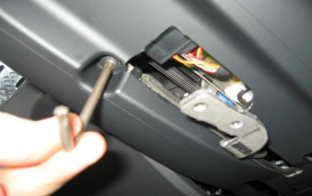
Step 1.2
When you screwed down both torx you can slowly pull the airbag from the steeringwheel. I say slowly because there will be one or two connectors behind it you need to disconnect with a tiny space.
Pull the orange clip towards you (see 2nd photo) to disconnect the airbag from the slipring and (optional) pull the MFSW connector from it's clip.


Step 1.3
When the airbag is out of the way you can start disasembling the steeringwheel. This is a TX40 screw. I pulled out the keys of the ignition and let the steeringwheel fall into it's steeringlock so I can set some extra pressure.
Audi made a notch so the steeringwheel can be perfectly aligned with the steeringhub when assembling back together. Try not to change the slipring position when pulling the steer of it's hub.


Step 1.4
If you'd only like to replace the steering wheel you can reverse the steps from here. If however you want to retrofit the CC aswell, please keep reading") .
.
To make sure your slipring doesn't move throughout the retrofit put some tape on it.
To reveal and remove the two TX25 screws please push the top steeringcolumn plate to the back and up, it's hold by two plastic clips on the side that will pop-off easily. After those two screws head down under and remove the bottom one aswell. It's next to the lever to change the steeringwheel positition.

Step 1.5
When all screws are disconnected gently pull the dashboard trim away. Safety first since there are a lot of fragile parts here.
After you removed the trim the steeringwheel unit (computer) will be visible. This unit is hold by 1 TX10 screw and two (easily breaking) plastic clips. The trick is to get your finger between the trims and press the back one and hold the first one with some kind of a screwdriver. Don't force it down, but don't be scared to give it a little push either.
When the unit is loose pull the slipring off by prying the top covers off. The whole ring will come of as one piece.


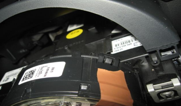
Step 1.6
The original blinker is being held on it's place by the clip on the side. Put a screwdriver in between it and gently pry the handle off by pulling it towards you.

Step 1.7
Now the stalk is off you can start disassemble it. I followed this video to disassemble the stalks and transfer the "new" stalk into the "old" one.
Step 2.
So, finally, step 2. When you got the stalk installed and tested you can proceed with the mirror.
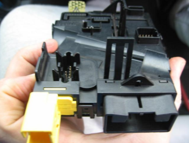
Get the mirror of by grabbing it by the base and turning it against clockwise (so to the left). and disconnect the 6 pin connector.

Comparison, top is only autodimming bottom is autodimming + HBA.


Step 3.
Screw down the trim holding the roof interior in the middle, this is done with a TX15.

Step 4.
Then whip out your interiorlight. The glass and fron trim can be removed without screws. The unit then comes out with 2 philips headscrews.


Step 5.
Now fiddle the cable inbetween the roof and tidy the cables. Connect the 8 PIN from the Kufatec cable to your HBA mirror and the 6 PIN from the Kufatec cable to the 6 pin connector that is on the original cable previously connecting your autodim mirror.


Step 6.
Get your A-trim loose if you want to put the Kufatec cable away tidy. You can just put a screwdriver inbetween and pull it loose. Then get your fingers under it and gently pull the trim towards you. When it's clicked loose you need to pull the trim up and it comes loose.


Step 7.
Then gently pull the cable under your steeringcolumn and get it away tidy. Disassemble the plate under your steeringwheel because now comes the last and most fun part of the retrofit.
(I know it's a cable retrofit mess in my A3, need to tape them in and tidy them up some weekend)

Step 8.
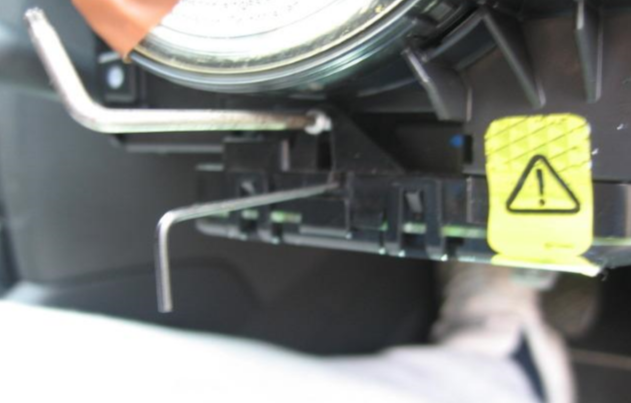
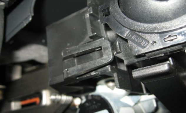
Pull the connector out of the CAN-Gateway and loose the connector housing from the actual connector so the pins are free. You have not much working space under the steeringwheel. I disassembled the A/C tube to give me some more room, this is only attached with 1 screw (TX25).

Step 8.1
On a LHD the CAN-Gateway is located above the gas pedal.
On a RHD the CAN-Gateway is located above the clutchpedal (not sure, can't confirm looked it up on internet.)

Step 9.
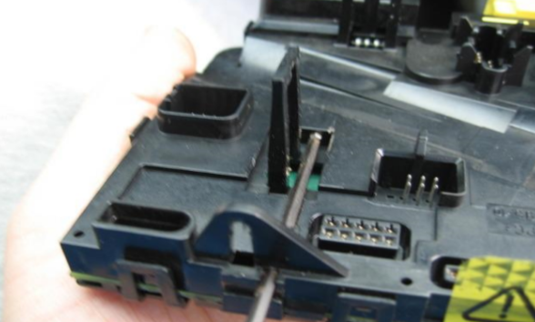
When the housing is off you can see the PIN numbers. You need to get 2 wires from this connector, CAN-High and CAN-Low.
PIN 6: CAN-Low (Orange)
PIN 16: CAN-High (Orange)
On the Kufatec cable the imprints on the cable will tell you wich one is which. I used T-connectors to connect these cables instead of splicing them into the exising looms, but this is personal preference. Since you don't have much working space I find it easier to just click the connectors around the cable and push them in instead of splicing, connecting and taping it off.


Step 9.1
Since I used T-Connectors the original housing won't fit anymore. So I took that and sawed a bit off with a knife. Fits perfectly after.


Step 10.
Now put everything back in reverse order. The only thing left now is coding the device.
1. First sign-on the device in the CAN-Gateway.
[19-CAN Gateway]
[Installation List]
20 - High Beam Assist

2. Now tell the BCM module the HBA mirror is installed.
[09-Cent Elec.]
[Coding-07]
[Longcoding Helper]
Byte 11
Bit 3 - Activate "High Beam Assist installed"


Result
When coded correctly the mirror should light up when the ignition is turned. There should be NO message on your DIS. If you receive the following message;
"High Beam Assist system failure/error"
Then you should check your CAN-High and CAN-Low. Maybe you connected them both the wrong way.
You can test the HBA by making the environment dark and putting a dark cloth infront of the scanner. After a few seconds the high beam should turn on.


Good luck!
Henkkeumus
Since there was litteraly zero information to be found about this retrofit I took my chances and did it myself.
So, this how-to; how to retrofit a HBA (high beam assist) mirror in your A3.
Before purchasing all the parts, please read the notes underneath to avoid disappointment.
Note: this retrofit only suits A3 MJ2010 and up. The earlier models don't have a BCM and CAN-Gateway that can handle the coding for this retrofit. You can however also upgrade the BCM and CAN-GW to do this retrofit. This is a pretty exspensive upgrade. I can't really give you exact partnumbers of what models will work together but I think if you rip them from a newer model it would do the job.
Note 2: Even if you have a MJ2010 and up you first need to check if your own BCM and CAN-GW can handle the coding. This retrofit addresses the PQ35 CAN-GW module. You can check the model with VCDS:
[19-CAN Gateway]
[Coding-07]
[Longcoding helper]
Note 3: You also need a blinker stalk that is spring loaded. This means that you need a highbeam stalk that will go back to middle/center position after you pushed or pulled it. This is because when the mirror HBA is enabled the stalk can't be stuck on high beam. If this is the case the computer can't turn the high beam off.
Used tools for this retrofit
- VCDS/VAGCOM
- HBA Retrofitcable from Kufatec: https://www.kufatec.com/en/volkswagen/vw-eos/high-beam-assist-hba-harness-for-pq35-38052
- Torx: TX15 / TX25
- Socket wrench: M8 / M10
- T-Connectors: https://nl.aliexpress.com/item/3265...earchweb0_0,searchweb201602_,searchweb201603_
Step 1.
Since I have retrofitted cruisecontrol stalk from an Audi TT I had the "old" blinker stalk. This stalk stays on it's position when pushed forward or pulled back. For this retrofit a stalk that will bounce back to middle/center position is necessary.
Step 1.1
Disasemble the original airbag. Turn your steeringwheel 90 degrees. This way you can remove the clips that will reveal the TX25 torx screws that will hold the airbag.
Step 1.2
When you screwed down both torx you can slowly pull the airbag from the steeringwheel. I say slowly because there will be one or two connectors behind it you need to disconnect with a tiny space.
Pull the orange clip towards you (see 2nd photo) to disconnect the airbag from the slipring and (optional) pull the MFSW connector from it's clip.
Step 1.3
When the airbag is out of the way you can start disasembling the steeringwheel. This is a TX40 screw. I pulled out the keys of the ignition and let the steeringwheel fall into it's steeringlock so I can set some extra pressure.
Audi made a notch so the steeringwheel can be perfectly aligned with the steeringhub when assembling back together. Try not to change the slipring position when pulling the steer of it's hub.
Step 1.4
If you'd only like to replace the steering wheel you can reverse the steps from here. If however you want to retrofit the CC aswell, please keep reading
.To make sure your slipring doesn't move throughout the retrofit put some tape on it.
To reveal and remove the two TX25 screws please push the top steeringcolumn plate to the back and up, it's hold by two plastic clips on the side that will pop-off easily. After those two screws head down under and remove the bottom one aswell. It's next to the lever to change the steeringwheel positition.
Step 1.5
When all screws are disconnected gently pull the dashboard trim away. Safety first since there are a lot of fragile parts here.
After you removed the trim the steeringwheel unit (computer) will be visible. This unit is hold by 1 TX10 screw and two (easily breaking) plastic clips. The trick is to get your finger between the trims and press the back one and hold the first one with some kind of a screwdriver. Don't force it down, but don't be scared to give it a little push either.
When the unit is loose pull the slipring off by prying the top covers off. The whole ring will come of as one piece.
Step 1.6
The original blinker is being held on it's place by the clip on the side. Put a screwdriver in between it and gently pry the handle off by pulling it towards you.
Step 1.7
Now the stalk is off you can start disassemble it. I followed this video to disassemble the stalks and transfer the "new" stalk into the "old" one.
Step 2.
So, finally, step 2
. When you got the stalk installed and tested you can proceed with the mirror. Get the mirror of by grabbing it by the base and turning it against clockwise (so to the left). and disconnect the 6 pin connector.
Comparison, top is only autodimming bottom is autodimming + HBA.
Step 3.
Screw down the trim holding the roof interior in the middle, this is done with a TX15.
Step 4.
Then whip out your interiorlight. The glass and fron trim can be removed without screws. The unit then comes out with 2 philips headscrews.
Step 5.
Now fiddle the cable inbetween the roof and tidy the cables. Connect the 8 PIN from the Kufatec cable to your HBA mirror and the 6 PIN from the Kufatec cable to the 6 pin connector that is on the original cable previously connecting your autodim mirror.
Step 6.
Get your A-trim loose if you want to put the Kufatec cable away tidy. You can just put a screwdriver inbetween and pull it loose. Then get your fingers under it and gently pull the trim towards you. When it's clicked loose you need to pull the trim up and it comes loose.
Step 7.
Then gently pull the cable under your steeringcolumn and get it away tidy. Disassemble the plate under your steeringwheel because now comes the last and most fun part of the retrofit.
(I know it's a cable retrofit mess in my A3, need to tape them in and tidy them up some weekend
)
Step 8.
Pull the connector out of the CAN-Gateway and loose the connector housing from the actual connector so the pins are free. You have not much working space under the steeringwheel. I disassembled the A/C tube to give me some more room, this is only attached with 1 screw (TX25).
Step 8.1
On a LHD the CAN-Gateway is located above the gas pedal.
On a RHD the CAN-Gateway is located above the clutchpedal (not sure, can't confirm looked it up on internet.)
Step 9.
When the housing is off you can see the PIN numbers. You need to get 2 wires from this connector, CAN-High and CAN-Low.
PIN 6: CAN-Low (Orange)
PIN 16: CAN-High (Orange)
On the Kufatec cable the imprints on the cable will tell you wich one is which. I used T-connectors to connect these cables instead of splicing them into the exising looms, but this is personal preference. Since you don't have much working space I find it easier to just click the connectors around the cable and push them in instead of splicing, connecting and taping it off
.
Step 9.1
Since I used T-Connectors the original housing won't fit anymore. So I took that and sawed a bit off with a knife. Fits perfectly after.
Step 10.
Now put everything back in reverse order. The only thing left now is coding the device.
1. First sign-on the device in the CAN-Gateway.
[19-CAN Gateway]
[Installation List]
20 - High Beam Assist
2. Now tell the BCM module the HBA mirror is installed.
[09-Cent Elec.]
[Coding-07]
[Longcoding Helper]
Byte 11
Bit 3 - Activate "High Beam Assist installed"
Result
When coded correctly the mirror should light up when the ignition is turned. There should be NO message on your DIS. If you receive the following message;
"High Beam Assist system failure/error"
Then you should check your CAN-High and CAN-Low. Maybe you connected them both the wrong way.
You can test the HBA by making the environment dark and putting a dark cloth infront of the scanner. After a few seconds the high beam should turn on.
Good luck!
Henkkeumus
