How to: Blank Dash Button mod for garage remote control

Hi Geoff, just done my soldering and want to check the led. Should it light up before I do anything else or do I need to connect it to the switched garage opener or whatever I'm connecting it to

Sent from my SM-G950F using Tapatalk
I've chosen to wire it into the one with no button, is that okay?
23581774cf5433112d8fe070e7117f21.jpg


Sent from my SM-G950F using Tapatalk
 
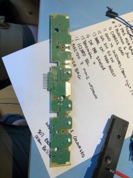
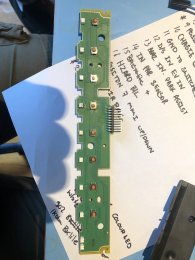
If you have soldered the resistor and led, the led should light up with the others, regardless of the switch. I tested mine out of the car (mainly because I haven't got the car yet!) using a 9v battery. Pin 11 is common -ve and Pin 5 is +ve for all led backlights except the hazard which is on a separate circuit.

That button is fine to use, it will be Pin 3 when the switch is soldered in place.
 
All the switches are push to make, momentary action only.

Thanks, looks like I need to find a latching PCB micro switch and replace it then, I will need it to be push to make latching so it can turn on and off the power to the front parking sensors.
 
Might be easier to get something like this

https://www.mrs-electronic.com/us-en/product/toggle-relay/

That way the momentary switch can become a toggle switch and isn't taking any current load either.

Your probably right, I was debating on using a timer circuit (555 or similar) but I suppose its safer to use a relay.

I was heading away from the relay route as many require a latching switch, but that seems to be a good relay in your link. Although not available in the UK from what I can make out.

Thanks
 
If you have soldered the resistor and led, the led should light up with the others, regardless of the switch. I tested mine out of the car (mainly because I haven't got the car yet!) using a 9v battery. Pin 11 is common -ve and Pin 5 is +ve for all led backlights except the hazard which is on a separate circuit.

That button is fine to use, it will be Pin 3 when the switch is soldered in place.
Hi Geoff, where do I solder the resistor on my point for that button position? I'm not very electrically minded lol

Sent from my SM-G950F using Tapatalk
 
Can I take a resistor off my donor board?

Sent from my SM-G950F using Tapatalk
Yes, if you can get them off OK but I found it more difficult than taking off the LED as they are so small. In the end I just ordered some new ones from RS components to save fiddling around.
 
1 ohm resistor in from maplins, no led? Is that the correct place for button 3?
142e62dbc00c878c8b0a0b82b38aaeba.jpg


Sent from my SM-G950F using Tapatalk
 
It looks like the right position but it should be 1k ohm ie 1000ohms, not 1 ohm. If it really is only 1 ohm you've fitted you might have fried the LED. I got surface mount resistors like the OEM ones, I'm not sure you will get the top cover back on with the resistor sticking up that far.
 
Ignore me finally got it sorted
9f8a998c5a2aec6a208e8696969aec8f.jpg


Sent from my SM-G950F using Tapatalk
 
  • Like
Reactions: Shawn8V, GeoffT and paul wev
Not sure about the different colour backlight, I think I would have gone with red, but it does make it stand out more I guess.
 
  • Like
Reactions: oli356
Did you make a template or did they do it ?
I'm a graphic designer. I designed the logo on my PC and sent them the files at the right size.

Sent from my SM-G950F using Tapatalk
 
  • Like
Reactions: Shawn8V and rcnacura
@rcnacura

I used these guys to laser etch a blank button with my garage door logo. They were very helpful and it gives a really professional result with whatever design you want and it can be backlit too. They are in Devon only about 25 miles from me so I drove there myself and they did mine there and then, but can do it by post if you aren't nearby. I would definitely use them again.

www.laserncreations.co.uk
Great contact. Thanks.
 
@SDB
Thats a really well thought out and presented mod.

I have recently retrofitted a full PDC to my A3 and was expecting to unclip a blank and just add the appropriate switch with light in the parking sensors position. No such luck as Audi make a gazillion switch variations depending on options but this mod will allow me to add the appropriate switch without having to replace the entire switch - Cost around £100 new.!!!

I am hoping to find a cheap donor switch containing the original Park Sensor graphics button and window in the frame.

Regarding the LED that illuminates above the switch when active, can you confirm if it has a series load resistor at some point between the input pin 4 and the LED or between the LED and earth. I cannot quite make it out in the pics and I'm cautious of damaging the parking module if I connect the LED without a resistor as I cannot assume there is one in the parking module output.

Thanks
You can find them much cheaper on AliExpress or used on eBay.

Sent from my Pixel 2 XL using Tapatalk
 
@SDB
Thats a really well thought out and presented mod.

I have recently retrofitted a full PDC to my A3 and was expecting to unclip a blank and just add the appropriate switch with light in the parking sensors position. No such luck as Audi make a gazillion switch variations depending on options but this mod will allow me to add the appropriate switch without having to replace the entire switch - Cost around £100 new.!!!

I am hoping to find a cheap donor switch containing the original Park Sensor graphics button and window in the frame.

Regarding the LED that illuminates above the switch when active, can you confirm if it has a series load resistor at some point between the input pin 4 and the LED or between the LED and earth. I cannot quite make it out in the pics and I'm cautious of damaging the parking module if I connect the LED without a resistor as I cannot assume there is one in the parking module output.

Thanks

If you want the indicator led you will have to get it engraved so it can shine through. I have a pile of parts from my latching switch mod PM me with what you need if you want to have a play and not just buy the correct part be aware the PFL back lights are red LEDs and FL switch pack is white LEDs if you look for a secondhand pack.

This is a pic of my fully populated switch pack
IMG 4450 IMG 4451


I also have some more photos in this thread

https://www.audi-sport.net/xf/threads/custom-laser-engraved-centre-switch-pack.378691/#post-3333832
 
If you want the indicator led you will have to get it engraved so it can shine through. I have a pile of parts from my latching switch mod PM me with what you need if you want to have a play and not just buy the correct part be aware the PFL back lights are red LEDs and FL switch pack is white LEDs if you look for a secondhand pack.

This is a pic of my fully populated switch pack
View attachment 167799 View attachment 167800


I also have some more photos in this thread

https://www.audi-sport.net/xf/threads/custom-laser-engraved-centre-switch-pack.378691/#post-3333832

Good point about the white LEDs for the FL version which is what I have.

Am I correct in thinking my best bet as I'm only looking to add the parking sensor button would be to try and source a used unit which has this button already then harvest that button, the amber on LED and resistor (if fitted), source a white led for the backlight as the donor is most likely red and use the frame with a ready made window above the parking sensor button.

This would also get over the issue which @GeoffT noticed that the buttons are slightly handed either side of the Hazard button.
 
This is a bit of a niche mod but someone out there may find it useful.

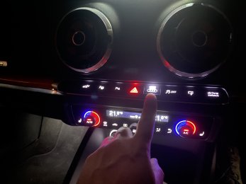
Making use of the spare Dash Buttons to activate an electric garage door or gate remote control is done in two stages; firstly convert the static buttons on your dash switch unit into moving buttons and secondly prepare the remote fob.
[where possible, use plastic tools when prising things apart otherwise you’ll damage or bruise the plastic]

First Stage:
Buy a second hand dash switch unit (e.g. ebay for between £15 - £20).
  1. Take the second hand unit apart in this order;
View attachment 132106
  • Remove the three torx screws (you’ll need a T8 torx bit) that holds down the large flat plastic moulding covering the pcb.
  • Remove the five torx screws securing the pcb and lift it out along with the rubber strip and put them safely to one side.
  • Remove the torx screws at the side of the unit (one each side) that hold the front mouldings in place.
  • Remove the chrome trim by carefully prising the clips over the black plastic tabs.
  • From underneath carefully prise off each of the switch covers (be careful – you will break some of the retaining tabs, fortunately the covers will go back on ok with one tab in tact).
  • The white moulding that was behind the ‘Passenger Airbag’ cover must be removed next.
View attachment 132107

  • Carefully squeeze together the two legs of the moulding at the same time pushing the moulding outwards. This plastic is very brittle and one of the legs will break if you squeeze too hard.
  • Once this is out, unclip the button frame (the moulding with the ‘windows’ for the buttons) from the body part by lifting the clips over the tabs of the body part.
  • The switch moulding plastic part (black is the moving one and white is the static one) is much more resilient, they are removed by squeezing both sides fully in (as shown in the picture) to free the sides from the pivot pins at either side and at the same time push the moulding outwards. Use two metal flat bladed screwdrivers (or long nose pliers) as it takes a fair amount of force to push the legs in. You only need the black switch mouldings, no need to remove the white parts from the sacrificial unit.
View attachment 132108

2. Take your unit out of the car using radio removal keys.
View attachment 132110
3. Strip it apart in the same way as above.
4. This time you need to remove the white static switch mouldings. Replace them with the black moving ones you removed from the other unit. They just push in and click into place.
5. Reassemble all the parts and turn your attention to the pcb’s

View attachment 132111

6. You need to ‘desolder’ the surface mounted switches from the second hand unit and solder them onto the blank spaces on yours (keep to the same orientation as the existing ones on the board).
7. I didn’t fit any additional led’s as I didn’t want any indication that the buttons did anything, but now is the time to do this if you want to.

View attachment 132114

8. Once you have all the surface mount switches on the pcb, assemble it back into the unit along with the rubber strip that acts as the ‘spring’ for the buttons. Fix the pcb in place with the five torx screws.

View attachment 132115

9. Put the cover back on and secure it with three torx screws.
10. Don’t forget the two torx screws for the side holes that hold the body to the ‘window’ frame.

In the car you will have seen the 20 pin connector from when the unit was removed.

View attachment 132117

For UK cars the button switch pin slots are;

1 = Drive Select
2 = Stop/Start
3 = Park Assist or Spare (right side of Stop/Start)
4 = Parking Sensors or Spare (left side of Hazard)
6 = Hazard
7 = Traction Control
9 = Spare (right side of Hazard)
11 = Common earth to all switches
17 = MMI Screen Up/Down

You’ll need a repair wire for these new connections (I had a spare loom from a footwell light install with the correct connectors on that I was able to use).

Plug the wire(s) into the empty slot(s) you want to use and run the cables behind the dash towards the fuse box, this is easier to do if the glove box is removed.

Second Stage:

1.
Take your remote control apart and identify how it switches, you’ll see mine had a small surface mounted switch which I removed. This was bridged with copper wire to complete the circuit.

View attachment 132125
View attachment 132126

2.
Solder two tails to the battery terminals. Put the covers back on to protect the pcb, after making a hole for the cables to escape.
View attachment 132127

3.
I connected these two cables into a small multi-plug connector (from Maplin). The mating half of the connector was wired up with the lead from the dash button and an ignition switched live from the fuse box.
4.
So once the two halves are pushed together the live feed goes to the positive terminal of the remote and the dash button cable goes to the negative terminal of the remote. The dash button completes the circuit when depressed, but only when the ignition is on.
5.
Tidy the cables up and hide the remote control behind the dash or glove box or end panel of the dashboard.
6.
Enjoy the new addition to the dash buttons.

Hope this is useful to someone.
Can you use one of the blank switch positions as an additional relay switch you have to click to allow StartStop ignition button to work (so without clicking to the on position the start stop ignition won’t engage)? (If so, how would it be connected up in a UK A3 8V FL for the same principle this guy achieved (but he used a Halfords switch instead)?
*** Please: For the sake of privacy of this type of mod and ensuring this mod can’t be easily searchable by those with not so great intentions, as you can probably see what is trying to be achieved by this, please don’t put any keywords that would describe what this would do thanks

a private message instruction list would be helpful as I’m a newbie without really any electrics knowledge but I could likely install a bridging cable if it’s straightforward
 
Search for my username on here I’m sure I put instructions up for how to do this with LED indicator etc
 

Attachments

  • 903DDE1B-223A-4114-B611-2D594B6B90CA.jpeg
    903DDE1B-223A-4114-B611-2D594B6B90CA.jpeg
    2.8 MB · Views: 141
  • 2255FE07-4068-4D9D-8BA7-DB18CC864CFC.jpeg
    2255FE07-4068-4D9D-8BA7-DB18CC864CFC.jpeg
    2.7 MB · Views: 148