Guide - How to fit a catch can and simplify the PCV system

Westy

Registered User
Joined
Dec 2, 2008
Messages
17,400
Reaction score
1,104
Points
113
Location
Cambridgeshire sometimes Hertfordshire
I've created this thread to try and put together a definitive guide that cuts out all the crap from this thread:

http://www.audi-sport.net/vb/a3-s3-...yone-including-pcv-system-simplification.html

PLEASE NOTE THAT SOME OF MY PICS ARE OF THE S3 BAY AND SOME OF A GOLF BAY SO SOME VALVES/PIPES MIGHT NOT BE ON ALL MODELS OF 1.8T ENGINE

Ok so firstly a little back ground into the PCV (positive crankcase ventilation) system and how it works in stock form:

pcvsystem.jpg


With the stock PCV system oil vapour burnt by the engine is vented from the rocker cover and is introduced to the TIP (Turbo Intake Pipe) on boost so that it is burnt in the combustion chamber with fuel and air. This design was due to the strict emissions rules that are in place when designing a car.

The problem with introducing oil vapour into the TIP is that oil gats into the boost system, intercooler(s), and throttle body. When burnt in the combustion chamber with fuel and air can reduce the octane level of the fuel and therefore effect performance.

Another problem with the PCV system is that over time the rubber hoses become clogged with oil and start to perrish which leads to splits and more issues.

The whole idea behind the catch can is to catch the vapour, remove the oil and return cleaner vapour into the TIP (when venting back to TIP), or vent to atmosphere for an even cleaner system.

A catch can with baffles works more efficiently at seperating the oil from the vapour but if you're unable to get one with baffles you can use wire brillo pads inside the can.

-------------------------------------------------------------------------------------------------


Right firstly you will need the following bits:

- Catch can. Ideally one with 19mm inlet/outlet

IMG_0270.jpg~original


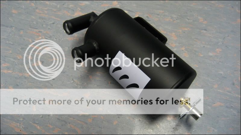
- 2 metres of 19mm oil grade hose

OilHoseR6-11.jpg~original


- 1x 19mm plastic t-piece

images


- 2x 90 19mm plastic joiners

plastic_90elbow_joiner.jpg

imgres
imgres
imgres


-------------------------------------------------------------------------------------------------

Now it's time to rip out all the old gear:

The whole lot should look like this when out:

3a.jpg~original


INSTRUCTIONS

(Taken from this thread: 1.8t - PCV simplification and catch can installation - uk-mkivs )


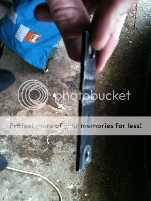
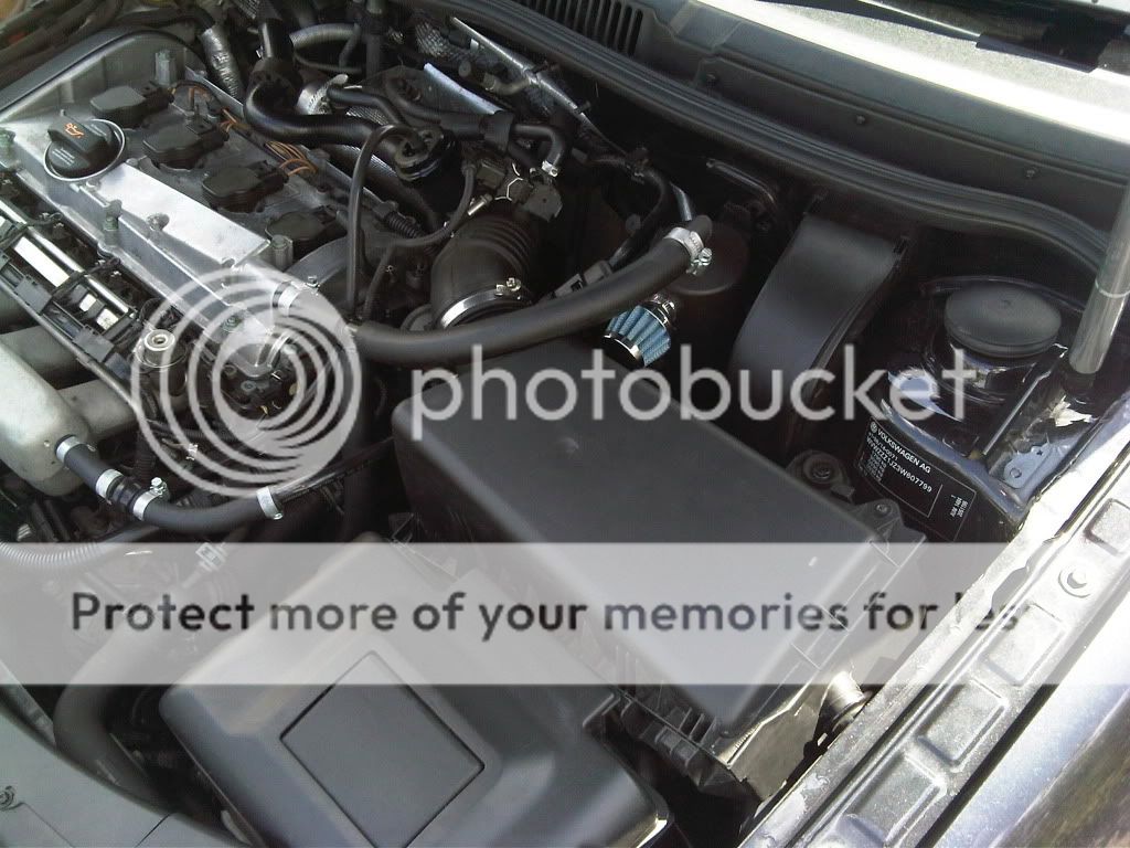
The first thing I did was to remove both engine covers. Under the lower cover I loosened the metal plate which houses the N112, the N249, a checkvalve and a small maze of vac pipes
2 x 10mm bolts holding the SAI (secondary air injection) pump inlet pipe

IMG_0239.jpg~original


then 2 x hex bolts holding the plate to the manifold

IMG_0242.jpg~original


Carefully lift the plate from out of the clip on the side of the dipstick holder. If your dipstick holder's never been replaced it'll be very fragile and it'd be a good idea to replace it now for what it costs (about £5-6)

IMG_0246.jpg~original


Now I started removing all the stock pipework from the top
See right behind the dipstick, there's the first small L section of pipe that leads to the suction jet pump Y piece. This is the pipe in which I've previously inserted a checkvalve, to stop boost before it hits the suction pump


IMG_0244.jpg~original


I removed that, leaving the suction pump end exposed


IMG_0254.jpg~original


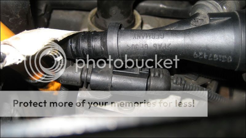
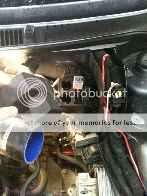
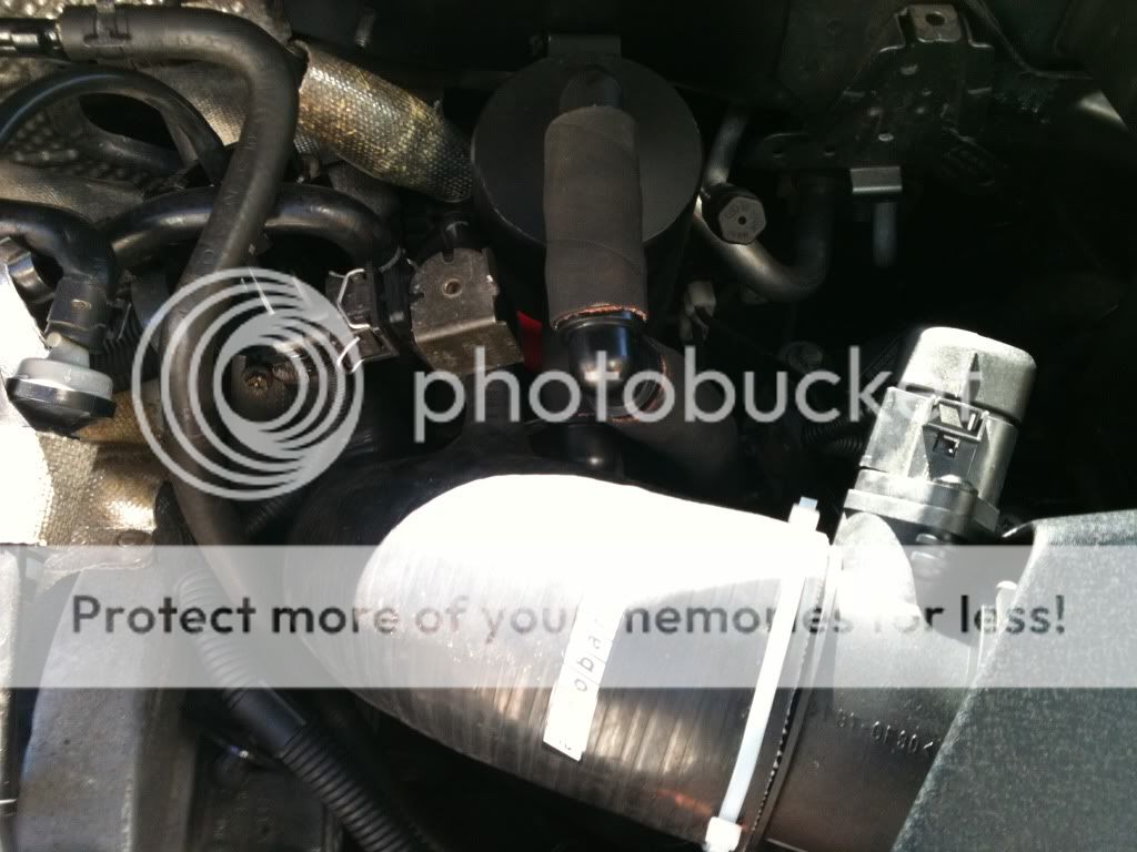
Next was the infamous for splitting upper breather, on the passenger side of the rocker cover


IMG_0249.jpg~original


It attaches to the TIP via the 'hockey puck' accumulator valve


IMG_0248.jpg~original


Removed


IMG_0252.jpg~original


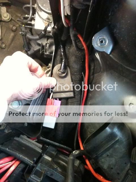
Then I disconnected the brake booster line, leading from the suction pump


IMG_0250.jpg~original


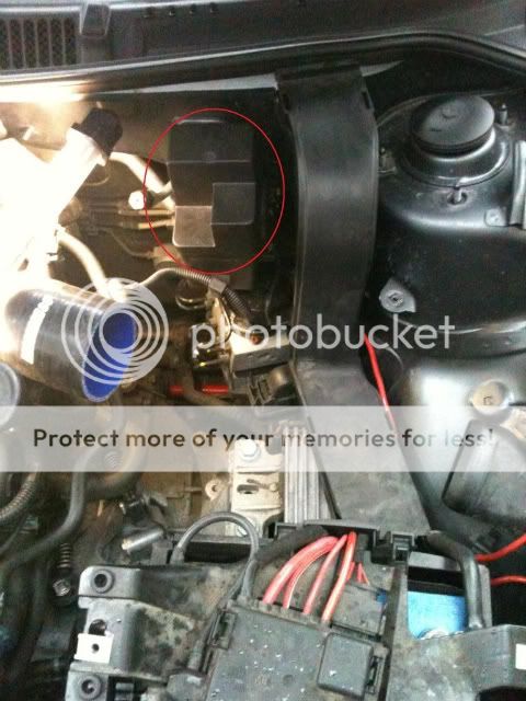
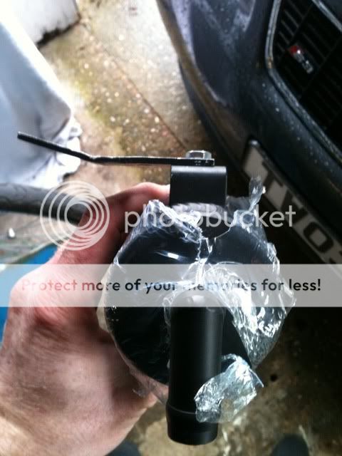
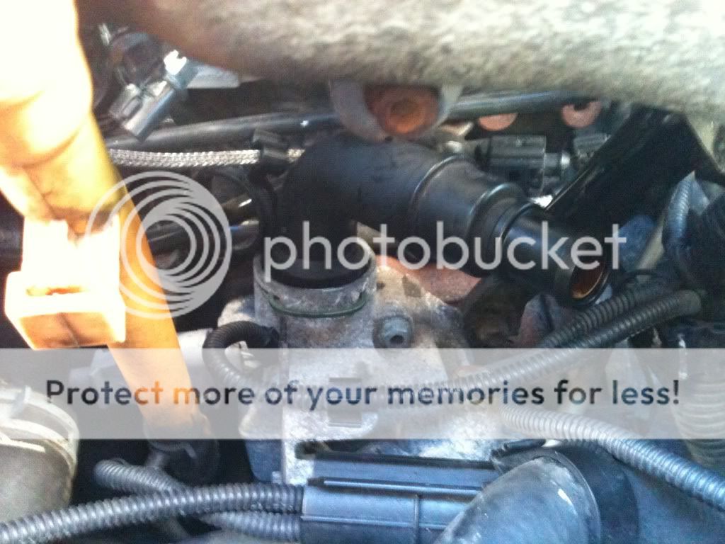
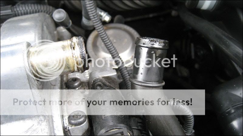
and finally I took out the lower breather pipe which is located right on the oil filter housing
You can see it on this picture from above, but unfortunately it's not in focus


IMG_0244.jpg~original


I used a long shafted flathead screwdriver to prise off the C clip that holds it in position


IMG_0245.jpg~original


There's an O ring in there too, careful not to lose it!
Removed


IMG_0256.jpg~original


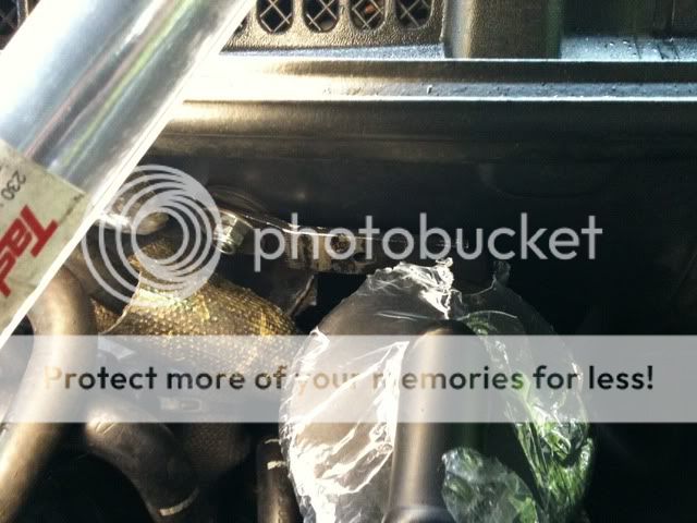
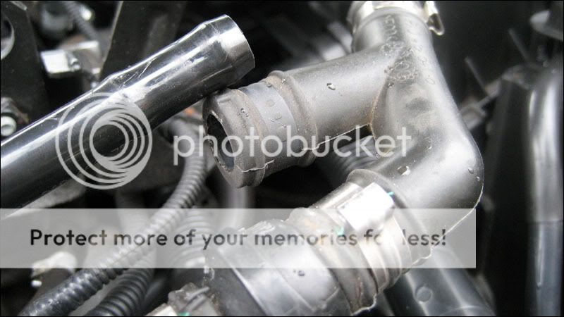
Now I managed to shimmy all the pipework clear and took this photo. The Upper breather Y pipe and the L piece leading to under the manifold are not attached, as mentioned above, I disconnected before removal


IMG_0255.jpg~original


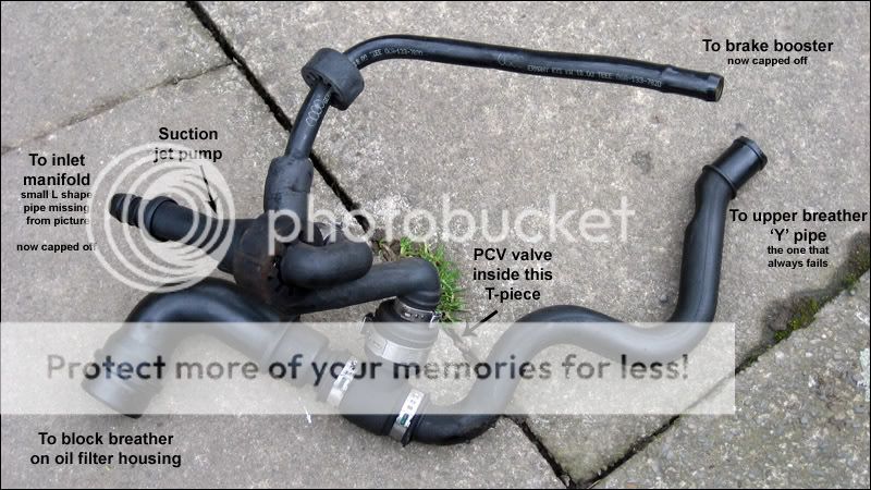
Yeggers! Look at that sludge that's accumulated
emotion-3.gif
Stuff like this clogs the PCV valve, the suction pump and will make it into your TIP..


IMG_0260.jpg~original


IMG_0262.jpg~original


Keep these 2 parts for the new installation


IMG_0268.jpg~original


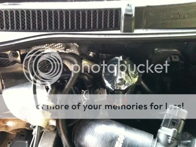
Now I want to cap the vacuum source under the manifold. It's not going to be used, all the pressure is positive coming from the crankcase and upper breather anyway and it'll be caught in the can. The fumes will also pull via the TIP connection when under acceleration. I used a small length of 3/8" ID pipe with a bolt screwed tightly into it


IMG_0286.jpg~original


This then fits to the nipple under the inlet manifold like so:


DSC00916.jpg~original


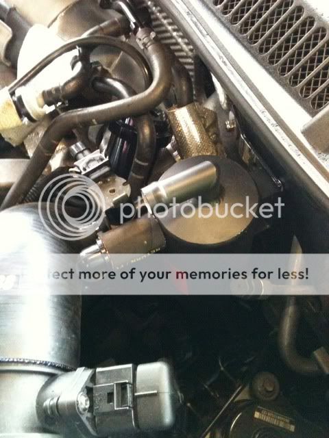
I'm also wanting to cap the brake booster line and just use the 1 vac source for brakes. It works on the AGU and ARZ so no reason it shouldn't work on an AUM right? I used a 1/2" piece of nylon rod and a jubilee clip but have since replaced this section of the brake booster line. Picture of revised piece to be edited in later


IMG_0282.jpg~original~original


Or alternatively use another screw:


DSC00886.jpg~original
 
---------------------------------------------------------------------------------------------------------------------------------------------------


Before fitting the new hose here is a quick overview of the pipe route:


Untitled.png~original


FITTING (VENTING TO TIP)


(Taken from Ollie H's instructions)


First off I removed the strut bar and the airbox to give myself some room:


Next, (thanks to a link from Imteyaz) was to get rid of the relay box shown circled in red above by relocating the relay inside it. (This will give more room to drain the tank from the side. It's not essential to remove this, but if left there you will have to drain the can by reaching under the TIP, where there is only a limited space)


0056A-1.jpg~original


First, remove the plastic cover from the cable run to the right of the box:


IMG_0057.jpg~original


Then remove the lid from the relay box:


IMG_0058.jpg~original


Remove the relay from the box and pull the cable clear:


IMG_0063.jpg~original


Now remove the relay box from the bulkhead.

Next, massage the relay and cabling into the cable run area:


IMG_0066.jpg~original


Then replace the cover and you are left with this:


IMG_0068.jpg~original


Next was the mounting of the can. The right hand stud shown on the last picture on post #208 was where I wanted to mount it, but I couldn't get a nut to match the thread type. I therefore decided to remove this stud altogether. I did this with a small cutting disc on a dremmel. At a later stage I will rub this down and paint it:


IMG_0070.jpg~original


I appreciate not everyone has a dremmel, but there is enough room to get an angle grinder in there aswell if you have one of these. If you have neither, you might be able to get a junior hacksaw in there, but if not all I can suggest is you ask a garage to cut it off for you. They normally have little air driven cutting discs for removing rusted exhaust bolts, so should do the trick nicely.

Now there's two options that can be taken here. The first is to drill a fresh hole in the firewall and use the pollen filter flap to put your hand in and pass a bolt through from the inside. I tried this but my hand was too big to get past the cable runs that are behind there. All I can suggest is that you give it a try yourself and see whether you can get your hand in there.


IMG_0126.jpg~original


The second option is to use the left hand stud on the firewall, which is what I did. In order to use it, you have to make some adjustments to the supplied bracket (or make a whole new bracket). First thing is to flatten the supplied bracket:


IMG_0071.jpg~original


Then using a vice, make a bend in the bracket which is roughly the same angle as the one on the firewall. Then attach it to the catch can:


IMG_0072.jpg~original


I then used one rubber washer and a couple of steel washers to mount the bracket on the left hand stud:


IMG_0075.jpg~original


IMG_0076.jpg~original


You will have to angle the bracket down slightly so that when you replace the strut bar, it does not catch the top of the can.

You can see from the following picture that the can is pushing up against the N75 valve, and also the aircon recharge pipe is pressed up against the side of the can aswell:


IMG_0077.jpg~original


I got around this by elongating the hole on the bracket and on the can, making the can sit more to the right. I then bent the aircon pipe over so it wasn't rubbing against the side. It does bend quite easily without damaging it, but if you do do this, be it at your own risk.


IMG_0079.jpg~original


The next job is how to route the hoses to and from the can. You can see from the above photos that the inlet and outlet from the can is quite close to the TIP, close enough that there isn't enough room to bend the hoses down under the TIP. You will therefore need to purchase two 90 degree pipe connectors, like these ones: http://cgi.ebay.co.uk/ws/eBayISAPI.d...=STRK:MEWAX:IT

They will point the hoses downwards like the following pictures show:


IMG_0078.jpg~original


IMG_0088.jpg~original


Next, attach the PRV directly to the TIP connection, in the same inlet/outlet configuration as before, just without the extention pipe. Point the inlet up towards the catch can:


PERSONALLY I FOUND THAT THE EASIEST WAY TO GET SOME OF THE PLASTIC CONNECTORS INTO THE HOSE IS TO USE SOME HOT WATER TO SOFTEN THE HOSE AND USE SOME WASHING UP LIQUID ON THE PLASTIC ENDS.


IMG_0137.jpg~original


This is what it looks like from the top:


IMG_0138.jpg~original


You can see that all I've done is use a 90 degree 19mm pipe connection to direct the can outlet downwards. You will need to play it by ear for the lengths of hose for this, depending on your can mounting position and TIP. My Autobahn TIP connection is in a slightly different position to the oem one.

Next, use another 90 degree pipe connector to point the can inlet down under the TIP, as shown:


IMG_0124.jpg~original


This will come down to the T-piece connection. Make sure you measure the length of hose right so that the T-piece is in line with the rocker breather connection.


IMG_0125.jpg~original


Then cut a suitable length of hose to pipe the t-piece upto the rocker breather


IMG_0134.jpg~original


The last connection on the t-piece is then to the crank breather. There isn't much room to feed the pipe through to the breather pipe where it normally is because of the coolant pipes that are there. Therefore, when I put the crank breather 90 degree pipe back in, I pointed it outwards towards the front of the car, rather than parallel to the block like it normally is:


IMG_0130.jpg~original


With the pipe connected, and the pipe routed underneath the throttlebody area:


IMG_0131.jpg~original


IMG_0132.jpg~original


Here's the finished product:


IMG_0141.jpg~original


---------------------------------------------------------------------------------------------------------------------------------------------------
 
Now a quick look at my install for further info and pictures:

ad481529.jpg~original


The top hose comes down under the TIP and joins to a t-piece. This then goes up to the rocker cover and off to the 90 degree pipe on the oil filer housing. Here you can see the rocker cover route:

ce8a8f39.jpg~original


Here is a close up of the T-piece taken from the left side of the battery:

4f357458.jpg~original


You cant see the hose from the top of the can in these pics but the red line shows the hose to the rocker cover and the blue line shows the hose off to the oil filter:

4f357458-1.jpg~original


Here is where it joins the 90 degree bend on the oil filter housing below the inlet mani:

31b6b597.jpg~original


So that's the top pipe on the diagram done. The side pipe out of the can goes down and into the hockey puck which then vents into the TIP as shown here:

d489bb6a.jpg~original


Red line shows the hose coming from the side of the can, hockey puck is obvious, the blue line is heading to the TIP and the green line is the TIP:

d489bb6a-1.jpg~original


With all that done that's the hard part. The easy bit is to block off the hose on the bottom of the inlet manifold:

All I did was cut a piece of hose and jubalee clipped in a bolt like so (pic taken through the gap of the inlet mani):

2614cd5c.jpg~original


Last thing to do is to sort out the hose that runs off the left hand side of the inlet mani that runs to the break servo:

41568fa7.jpg~original


Now the silver bit in between the 2 90 degree silicone is the 1 way valve which ensures you have servo'd brakes. The hose then just runs up to the hard pipe along the firewall. Not the hose with ASH on it but the one to the right of it:

27aef301.jpg~original


Now obviously I bought spanking new pipes for the brake servo bit but you can just re use most of the stuff you ripped out and the 1 way valve that was already there. The original 1 way valve was a T-piece 1 way valve so you will need to block off the bottom of the T as described earlier in this thread.


-------------------------------------------------------------------------------------------------------------------------------------

I will post up some new pics next week showing how to vent to atmosphere for those that would rather do that. I've ran my system for nearly a year now and I still get the odd bit of oil in my boost system so i'm hoping an atmos vent will help a bit more.

Basically though you ditch the outlet of the can that goes into the TIP and replace it with a breather like the following picture. You then bung up the TIP hose where the can used to go into:

IMG00356-20100629-1340.jpg~original


I hope this thread helps and if it doesn't I really dont know how to make it any simpler.

If you have any questions let me know.
 
  • Like
Reactions: hydro s3, bentwenty, Shoomakan and 2 others
Great write up mate I'm going to give this a go at some stage thanks
 
  • Like
Reactions: *ian*86
If I ever get round to doing another S3 install I'll take my own pics as I think I could make this even simpler just for S3 owners. Once you've got the thing installed and you can see how much simple the PCV system is you'll wonder how you ever struggled to understand it before ;)
 
Excellent thread, had some uncertainties before, but having read through this, I am more than confident.
The hose, T-piece and joiners are easy enough to find, can anyone recommend a suitable baffled catch can with 19mm inlet/outlets?
 
Hi just want to thank you for doing this I only sugested it yesterday :yahoo:
 
I too am after a 19mm catch can, also did I read somewhere that you can ditch the Hokey Puck thing.
 
Any catch can, even if it's made from an old baked bean tin will still catch something. Personally I'd try to get an average priced baffled can (think mine was £60ish) but if not, a cheap eBay jobbie with a few wire brillo pads will do.
 
Bit of late night mechanics tonight. Started by just wanting to fit a breather so I could vent the can to atmosphere instead of back to the TIP and ended up re-doing all the pipe work.

Started by getting the airbox out of the way. You can see my PCV system clearly this way:

d84a3645.jpg~original


fe2ed0ac.jpg~original


I then pulled off the bottom hose from the catch can which was going through the hockey puck and venting back to the TIP. I found that the can wasn't attached to the bulkhead any more where it appears to have rattled off the nut!

9db14ea2.jpg~original


This is the standard bracket on my catch can and you can see where the washer has been rubbing:

075d6e23.jpg~original


And this is where it was attached:

a61dbd1f.jpg~original


I had another bit of bracket that came with the can so I fiddled about with that to see if I can make the can a bit more accessable:

8b696c68.jpg~original


But in the end I just decited to fit it back to where it was using the lower hole so the can was raised up more. This meant I could shorten the route for the gasses and also makes emptying the can easier.

c62535b7.jpg~original


f309183f.jpg~original


With the can where I wanted it I re-directed the route from the oil filter housing using the 90 degree joiner that was originally used to vent back to the TIP. You can see some of the gunge from the oil fumes:

de98c6a0.jpg~original


Take a look at the hockey puck! This was brand new less than a year ago and where it was squashed along side the airbox it has been bent due to the heat and as a result it now flows both ways! In the bin it went. Dont need it now I'm venting to atmos anyway:

5bdc2c5b.jpg~original


Ok oil breather on and airbox back in only left me to connect up my shorter route of hose:

b342def2.jpg~original


And all done:

8ee51313.jpg~original


814925f5.jpg~original


I started up the car and left it for a good 5 mins to see if there was any issue with fumes from the breather but all seems ok so far. If it does become an issue I will use some spare hose and route the breater low down in the engine bay.

Hopefully this will keep a bit more oil out of my boost system.
 
quality mate il be doing that soon its also answered my question about the use of the hockey puck.
 
Well I knew I'd need to change my route when I got my Badger 5 TIP as it takes up a lot more room. The way I've routed it this time is the same way S3baby has routed his and it goes over the B5 TIP just fine. I think my only issue will be with the location where my can is mounted as the B5 TIP has the N75 hose location a bit further back then my Autobahn TIP.
 
Im going for one of those soon as i have enough saved up, so will be interested to see it routed on your pictures.
 
Just to let you all know that I had no issues with fumes on my way into work this morning. I gave it a load of beans and then sat in traffic with windows up and blowers on and it's all good.
 
Has anyone fitted a 1L Mocal can to their car? I have a spare left over from an old build.
 
You can see it here in the rather sparce (in comparison) engine bay of my old car in the UK (top right):
engine3.jpg


I think it has 15mm connections from memory. I may buy a new one though. My S3 has a split in the hard plastic hose that joins near the the "hockey puck" from under the inlet and I can smell it unless the AC is on recirc. Would I get the same odour with a catch can and filter attached like the one below?

Canton Racing Breather Catch Tanks #23-030PC | eBay
 
You'd be lucky to fit that mocal one in an s3 bay! I'm struggling with where to put mine.19mm outlets isn't a massive deal as you can get reducers to match the pipe work.
 
I know Westle recommends 19mm mate but there bloomin hard to find, I have seen a decent one on eBay in black (OEM) style, not bad priced either, its not baffled but im sure I read on here stuffing it with brillo pads works well though. Also it only has 15mm in and out . This is not a problem for the top one as a filter can plonk strait on it, but iv seen a 19mm to 15mm reducer to keep the piping all 19mm up to the catch tank. Only other way is maybe unscrewing the 15mm nipple and fabricating a 19mm one hopefully with the same thread size as it does look big enough to do.


Here's the one I am looking at. UNIVERSAL QUALITY BLACK ALUMINIUM OIL CATCH TANK KIT | eBay UK
 
Last edited:
Hand-operated drain **** facilitates tank cleaning lol
 
lol American descriptions are always strange haha. Wonder what they mean by (non hooded filtered breather), looks the same as a K&N filter. Looking at it it does look pretty smart though, I like that its 19mm too you will have to keep us posted when it arrives and what its like quality wise, but I must say I am tempted.