

Hi everyone,
I think I’ve finally plucked up the courage to actually get on and fit this kit. I’m pretty decent with a spanner and I’ve fitted head units before (back in the day) but never a setup with an amp/sub connecting into a factory install before - so please forgive my ignorance here! My car is a bog standard Bose setup with Audi Chorus single DIN cassette head unit with 6CD changer in boot. It’s never been touched in its life so I’m hoping that in order to install the AMSS sub and amp properly, I have all the correct components/cables/adapters and connectors before I begin dismantling.
I have the following:
1 x AMSS with JL Audio sub (6w3v3 model)
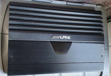
1 x Alpine MRV-T500 amp (good for standard headunits and the existing Bose speakers - 2 channel bridged into 4Ohm)
1 x Autoleads PC9-408 adapter (allows me to connect amp to headunit with RCA leads if I’m not mistaken).
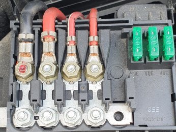
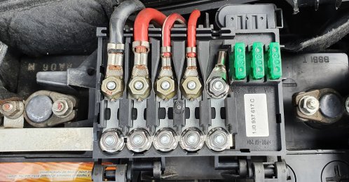
1 x variety of swanky heavy cables (pictured)
I’m trying to effectively replace the tupperware Bose sub and get some decent punchy bass out of my existing speaker setup. I have the excellent instructions by the late Andy Mac to follow but before I start - have I got everything? I’ll be honest some of the harness pinouts don’t mean much to me so, again, if anyone can dumb that down a little for me it would be appreciated.
Is there anything glaringly obvious that I’m missing?
Any advice you can give me regarding the connecting and setting up of the amp to the headunit would be super appreciated. I’ve read countless threads and posts about the AMSS (including <tuffty/>‘s thread). Andy’s instructions refer to a special harness he has made but I think the Autoleads adapter I referred to earlier achieves the same thing, right?
Anyway - tips and advice would be appreciated if you can assist. I’ll post updates of how I get on. Has anyone got an electrical diagram of the AMSS setup I could follow?
Here is a pic of the bits (with cables) I’ve collected over the years that is ready to fit:


I think I’ve finally plucked up the courage to actually get on and fit this kit. I’m pretty decent with a spanner and I’ve fitted head units before (back in the day) but never a setup with an amp/sub connecting into a factory install before - so please forgive my ignorance here! My car is a bog standard Bose setup with Audi Chorus single DIN cassette head unit with 6CD changer in boot. It’s never been touched in its life so I’m hoping that in order to install the AMSS sub and amp properly, I have all the correct components/cables/adapters and connectors before I begin dismantling.
I have the following:
1 x AMSS with JL Audio sub (6w3v3 model)
1 x Alpine MRV-T500 amp (good for standard headunits and the existing Bose speakers - 2 channel bridged into 4Ohm)
1 x Autoleads PC9-408 adapter (allows me to connect amp to headunit with RCA leads if I’m not mistaken).
1 x variety of swanky heavy cables (pictured)
I’m trying to effectively replace the tupperware Bose sub and get some decent punchy bass out of my existing speaker setup. I have the excellent instructions by the late Andy Mac to follow but before I start - have I got everything? I’ll be honest some of the harness pinouts don’t mean much to me so, again, if anyone can dumb that down a little for me it would be appreciated.
Is there anything glaringly obvious that I’m missing?
Any advice you can give me regarding the connecting and setting up of the amp to the headunit would be super appreciated. I’ve read countless threads and posts about the AMSS (including <tuffty/>‘s thread). Andy’s instructions refer to a special harness he has made but I think the Autoleads adapter I referred to earlier achieves the same thing, right?
Anyway - tips and advice would be appreciated if you can assist. I’ll post updates of how I get on. Has anyone got an electrical diagram of the AMSS setup I could follow?
Here is a pic of the bits (with cables) I’ve collected over the years that is ready to fit:
Last edited:


 quality write up as well

 well done!


 and working out all the best settings etc.
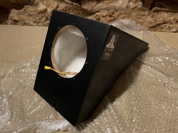
 I will consider relocation of the pump should it be absolutely necessary I have the tube and connectors in my parts department.