Access to Elsawin

youngn

Registered User
Joined
Nov 21, 2014
Messages
17
Reaction score
0
Points
1
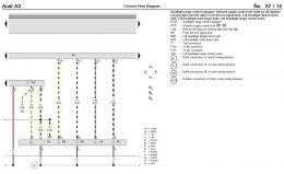
Hi guys does anyone have access to elsa, i ourchased some disks and i believe mine is corrupt. Can someone kindly upload a pic of the AUDI a3 2009 halogen headlight wiring diagram as well as the 2010 version

Thaks Guys
 
2009
A3 left headlight 2009 A3 right headlight 2009

2010
A3 left headlight 2010 A3 right headlight 2010
 
  • Like
Reactions: doctor46goat and youngn

thanks for that buddy you are a life saver.

My car has 9 pins in a 10 pin connector plug and it is a 2009 facelift model. 3 of those 9 pins belong to brown wires. However on the diagram it only shows there being one brown wire :S Is there any way to find out pin number or which pin number does what?

Im trying to retrofit some fron LED BI xenon lights and trie to follow the 2004-2008 wiring diagram but failed.

Thanks again
 
On all 4 of those diagrams it shows 3 brown wires actually going to the headlight unit. They are all common Ground wires.
I can see from that statement that you don't understand how the wiring diagrams work. This is a nice simple one so I will attempt to explain.

A3 left headlight 2009 annotated


The international standard used for the wiring designation numbers is DIN72552

http://en.wikipedia.org/wiki/DIN_72552

From the above you should be able to work out what color wire connects to what bulb and what pin.
If you thinks somethings useful you can click the like button.

Karl.
 
  • Like
Reactions: doctor46goat and youngn
On all 4 of those diagrams it shows 3 brown wires actually going to the headlight unit. They are all common Ground wires.
I can see from that statement that you don't understand how the wiring diagrams work. This is a nice simple one so I will attempt to explain.

View attachment 47733

The international standard used for the wiring designation numbers is DIN72552

http://en.wikipedia.org/wiki/DIN_72552

From the above you should be able to work out what color wire connects to what bulb and what pin.
If you thinks somethings useful you can click the like button.

Karl.

Hey Karl, you genuinely are awesome.
A guy was trying to charge me £30 just for the elsa diagram :/ and you just explained it all to me!

Thanks again
 
Also Karl, i have this from another thread on this forum

10 PIN adapter 14 PIN adapter
Pin 1-3 empty. 1-4 pin empty unless adaptive?
Pin 4---DRL/parking----10 pin led power
Pin 5------Ground--------5 pin ground
Pin 6------lowbeam------6 pin Hid power
Pin 7------Ground--------7 pin ground
Pin 8-------Highbeam----13 pin side markers
Pin 9-------Turnsgnl------9pin turnsgnl
Pin 10-----Sidemarker----12 pin DRL/parklmp/led

I understand the above 10 pin configuration is from a 2005-2008 Halogen Lamp, however, do you think the LED (14 pin) config has been written correctly as above?

If so i can then look at the diagram you provided and then match them up with the 14 pin connector!
 
Also i have managed to interpret the diagram resulting in this:

10 pin connector

1-
2-
3- Earth
4- DRL & Side Light
5- Earth
6- Dipped Beam Bulb
7- Earth
8- Main Beam Bulb
9- Turn Signal
10- Blank

The only thing i can't figure out is what 1 and 2 could be, the key doesn't really match up with those :/
 
Hey Karl, you genuinely are awesome.
A guy was trying to charge me £30 just for the elsa diagram :/ and you just explained it all to me!
Thanks again
£30 jeez maybe I ought to start charging that took about 5 minutes to find and post.
The connections to 1 and 2 are for the headlight adjustment motor that raises and lowers the beam.
 
  • Like
Reactions: youngn
Nice one Karl! Haha i know and a lot of people who start charging for information, actually gained the information from the forums :/

Can pin 1 and 2 be switched around?
 
No as they are polarity sensitive.you would be trying to make the light go up and it would be going down.

Karl.
 
  • Like
Reactions: youngn
Thanks Karl! Learning a hell of a lot. DO you think you can do me one last favour with Elsawin?

If only i could acquire the wiring diagram for the LED drill bi xenon uk lights i can then figure it all out. Would you able to provide this?
 
Upload 2015 1 8 16 57 1


Upload 2015 1 8 16 57 41


Upload 2015 1 8 16 58 51

Upload 2015 1 8 16 59 37


Hopefully you can work out what you need from these. A little more complicated than the halogen one but still reasonably straightforward compared to some of the wiring diagrams.
Karl.
 
  • Like
Reactions: youngn
If you think a post is useful or you like it you can hit the like button.

Karl
 
  • Like
Reactions: youngn
Hey Karl, i liked them all!

So i have managed to come up with a wiring diagram :/
DO you think this looks correct:

10 Headlight Control Motor 1-1 headlight control 14
10 Headlight Control Motor 2-2 headlight control 14
Earth 3-3 headlight control 14
DRL & Side Light 4-4 headlight control 14
Earth 5-5 Earth
10 Dipped Beam Bulb 6-6 Gas Discharge Unit
Earth 7-7 Earth
Main Beam Bulb 8-13 X Blank
Turn Signal 9-9 Turn Signal
X Blank 10-12- DRL/ Parking Lamp/ LED

goes to ECM - 11 Dipped Beam
goes to ECM - 12 goes to ECM
X- 13 Sidelight Bulb
X- 14-X

I also got some help from the thread below but its got me so confused
http://www.audi-sport.net/xf/threads/drl-bi-xenon-2010-wiring-2010-cemc-module-please-help.166171/
 
the middle numbers are pin numbers. The numbers on the left are on the 10 pin halogen connector and the numbers on the right are on the 14 pin. I have worked this out on the basis that i cut the 10 pin connector off

Been at it for over 4 hours today :O
 
Last edited:
I can see why you would be confused trying to do this. There is a significant difference in the way these 2 headlamp units work. Had a quick look through the thread you linked to and there is a lot of info in there.
The headlight level adjuster in a bi-xenon light has 4 connections and works differently to the headlight adjuster in a halogen light that has 3 connections. They aren't pin for pin compatible.
In a bi-xenon light the head lights are constantly moved to take into account vechicle loading to stop dazzling other users.
Extra wiring connections need to be made to the modules to get the BI-xenon functionality and you need to alter the modules coding so that it all works.
 
  • Like
Reactions: youngn
I can see why you would be confused trying to do this. There is a significant difference in the way these 2 headlamp units work. Had a quick look through the thread you linked to and there is a lot of info in there.
The headlight level adjuster in a bi-xenon light has 4 connections and works differently to the headlight adjuster in a halogen light that has 3 connections. They aren't pin for pin compatible.
In a bi-xenon light the head lights are constantly moved to take into account vechicle loading to stop dazzling other users.
Extra wiring connections need to be made to the modules to get the BI-xenon functionality and you need to alter the modules coding so that it all works.

Thanks for the reply Karl.
Basically i understand that in order for me to do a full functioning MOT passable retrofit i would need to install washer jets etc.

But what I'm trying to achieve is what a lot of the forum members have which is going from halogen to bi-xenon.
I believe pins 1 to 4 are for the levelling system on the 14 pin connector belonging to the bi-xenon lamp. However from what the person has posted on that thread i have tried to match it up as best i could. I understand that there is supposed to be a total of 2 wires which is to be connected to the CEM. However the part which i don't understand is where he has written for example:

Pin 10 (blank) wire of the halogen setup on the car connects to the 14 pin connector at pin 12 which is responsible for the DRL/ Parking Lamp/ LED

Surely that doesn't make sense because if DRL/ Parking Lamp/ LED is not being connected to anything as pin 10 is blank (no connection there) then where is the wire supposed to go? is it supposed to just float around?
 
Also when looking at the info the user provided on that thread it says the following:

DRL & Side Light 4-4 headlight control 14

Aka - pin 4 of the halogen 10 pin halogen connector responsible for the DRL and sidelight connects to pin 4 (14 pin connector) the headlight control of the bi-xenon lamp which is responsible for the headlight control. Sorely this is wrong? Or am i reading what he put wrong and mis understanding it
 
As there is no DRL's in the halogen light why would you have a connection to the headlight unit unless there is an option on another light unit. It does seem there are contradictions .
Looking at what Kufatec does

http://www.kufatec.co.uk/shop/en/au...d-headlights-adapter-audi-a3-8p-8pa-facelift2

It seems that depending on what module you have it may need changing out as well.Do you have the correct control unit ?

Karl.

Hey Karl,
Yes i have the correct control unit, The same one as the user on the thread. When i go into he long coding helper via CDS there are options for bi xenon etc.

I know its all confusing the hell out of me. People have purchased the adapters for the 2009 facelift a3's but they are also wrong. Which is why the user in that thread had to dismantle his kufatec adaptors and start fresh
 
TBH if Kufatec can't get it right then you are going to struggle. Good luck.
 
I just downloaded the program and I am having a difficult time using it. It is all in German, how can you change the language?
 

Similar threads

Replies
12
Views
5K
Ads
Replies
10
Views
3K
Replies
3
Views
1K
NHN
Replies
12
Views
1K