Reverse camera

CK87

Registered User
Joined
Apr 2, 2019
Messages
131
Reaction score
12
Points
18
Location
Netherlands
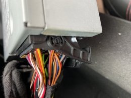
I bought a reverse camera kit and according to the manual found on this forum, I have to connect 2 pins into the quadlock 12-pin connector (CAN High and CAN LOW). Now, if I'm correctly, there is a chance that those slots (6 and 12) already got existing pins inserted.

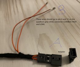
The cable that came with the camera kit that should be connected to pin 6 and 12 is shown on the attached picture.
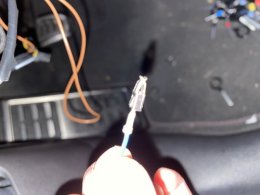
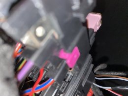
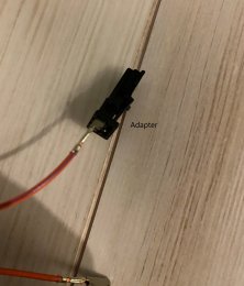
I see that they included a spliced connection with a black adaptor on it (A on the picture). I assume they made it so that I can pull the existing CAN High and Low wires (6 and 12) out of the grey-white (quadlock) connector and then insert the pins (B on the picture) into the grey-white connector? Could it be the idea of this is just like splicing wires?

Now my question is: the slots in this adapter is just large enough to fit these quite small (see picture) pins so I wonder if the pins of the existing CAN wires in the grey-white connector will alsof fit in this adapter?

Hopefully someone can give some information , thanks in advance
 

Attachments

  • a.jpg
    a.jpg
    1.6 MB · Views: 330
  • b.jpg
    b.jpg
    1.3 MB · Views: 262
Yes, they should fit just fine, the kit I installed a while ago did have the same connectors, I believe they exist just to simplify or have a more "elegant" way to tap into the Canbus signals without splicing cables.
 
Yes, they should fit just fine, the kit I installed a while ago did have the same connectors, I believe they exist just to simplify or have a more "elegant" way to tap into the Canbus signals without splicing cables.

Thanks for replying!

I placed the camera module bracket in the OEM location (rear right corner of the boot, it's an 8V sportback). There must be a earth point nearby? (since the earth wire is not that long)
 
Yes, for the sportback I believe it should be just above the wheel well

IMG 7857


Not my image :)
 
Thank you so much! Though I wonder how come the quad lock wont pop out of the mmi? I already unlocked it at the bottom. Its just wont budge
 
See picture
 

Attachments

  • EFE6E81E-1EC8-4E63-AE40-1711E021E77F.jpeg
    EFE6E81E-1EC8-4E63-AE40-1711E021E77F.jpeg
    83.8 KB · Views: 243
It should just pop out by moving the tab (it will push against MMI and pop the quadlock):

Upload 2020 10 24 8 38 38


Try to wiggle it a bit once the tab is moved (once again not my pic :))

Cheers!
 
Yes it was just a matter of pushing harder then expected!

so im doing the boot handle now. still figuring out how to reach the side clips to get it out. Because when i only compress the middle clips, it still wont move. Prying from the outside was not recommended according go the guide because of beaking the side clips. Any suggestions?
 

Attachments

  • E307B566-A6E1-43F6-9042-E793FBA8516B.jpeg
    E307B566-A6E1-43F6-9042-E793FBA8516B.jpeg
    87.7 KB · Views: 203
Mine was a saloon but it was just a matter of removing the 2 bolt nuts, uncliping the center clip and pushing from the inside while squeezing on the sides, if you look into the new handle (the one with camera) you will be able to see the clips/notches holding the handle in place.
 
Currently i only need to insert the wire in the fuse box. Though I think the pin is not the right one because when I want to insert it to the fuse box, the pin wont go further halfway the slot and it also can easily be moved out very easily
Can you confirm this means is indeed about having not the right one?
 

Attachments

  • 28572D6D-E1A7-4CC5-B93C-0CD5E0E1AD1B.jpeg
    28572D6D-E1A7-4CC5-B93C-0CD5E0E1AD1B.jpeg
    66.2 KB · Views: 223
  • 3765DAE7-AD7A-4E36-9C8E-A7B10EAD93E4.jpeg
    3765DAE7-AD7A-4E36-9C8E-A7B10EAD93E4.jpeg
    66.4 KB · Views: 216
  • 2C717C85-8A5F-4066-AC28-5E95E0BB167C.jpeg
    2C717C85-8A5F-4066-AC28-5E95E0BB167C.jpeg
    71.9 KB · Views: 221
Currently i only need to insert the wire in the fuse box. Though I think the pin is not the right one because when I want to insert it to the fuse box, the pin wont go further halfway the slot and it also can easily be moved out very easily
Can you confirm this means is indeed about having not the right one?
Correct “pin” for mini fuse slot. You need to release the purple locking mechanism in order to insert and the close the mechanism to secure.
 
Yes , i realised I missed the part of unlocking of the purple tab. Will try it soon!
I guess this could explain why I wasn't able to insert the wire fully, it got stuck just about halfway
 
Correct “pin” for mini fuse slot. You need to release the purple locking mechanism in order to insert and the close the mechanism to secure.

Can you, or maybe someone else, tell me how to remove the pink tab? Is het by just use force pulling toward you or is it backwards (away from the fuse box? When i want to pull it to me and i already that with some forse, it is blocked by some small black piece. It can only move a little bit, or is that actually the unlocking so that i have to insert it while pulling on it?
 

Attachments

  • B0209827-86F9-41C2-8349-969A7A07FC0F.jpeg
    B0209827-86F9-41C2-8349-969A7A07FC0F.jpeg
    78.4 KB · Views: 213
Last edited:

Similar threads

Replies
4
Views
928
Replies
8
Views
1K
Replies
2
Views
1K
Replies
2
Views
1K