I've finally started working on it again!
First up, the bulkhead.
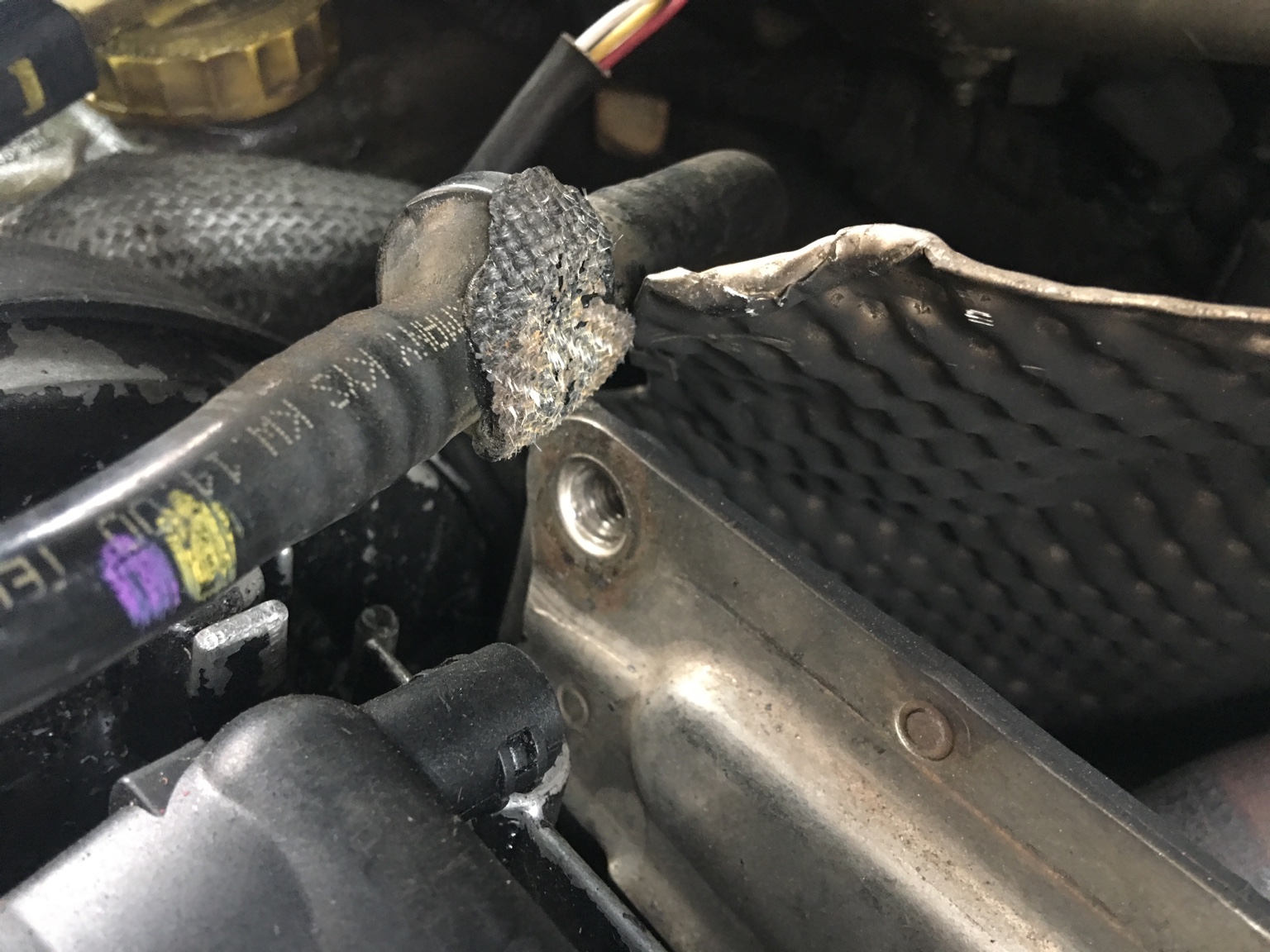
I stripped down my heatshielding, to reveal the mass of brake pipework behind.
I still had the original bulkhead sound deadening installed also, which had seen so many driveshaft failures, oil leaks, coolant leaks, and road debris, it weighed about 5kg and was probably a huge fire hazzard!
Obviously that had to go!

After removing the ABS pump and lines, i cleaned up the bulkhead, then set to work on the first brake line.
I mounted the T piece for the front split in an appropriate location, cut and bent the first pipe, flared both ends, and offered it up.
It didn't fit!
Argh.

It turns out, all the threads on the car are m10x1, apart from the 2 into the master cylinder! These appear to be m12 fine.
I cut the end off, and refitted one of the original fittings:

With a bit of practise the flares all seem to be coming out very well. I've found a drop of brake fluid on the pipe before flaring really helps get good results
")
So, attempt 1:

And it looked absolutely *****!

Lets try again:

Similar profile, but far less messy. That'll do.
Next up the front left wheel.
I started at the wheel arch end, replicating the factory shape as closely as I could:

Then moved onboard, trying to retain the stock pipe clips the whole way across the engine bay:

2 things to note when making brake lines:
If using copper, it absolutely MUST be clipped every ~200mm. Copper work gardens with vibration, and it allowed to vibrate around too much it can go brittle and crack.
You should also avoid a straight run between 2 fixed points, as it won't allow for any expansion or contraction with changes in temperature. S bends or similar before fittings are always a good idea to allow the pipe a little movement if required.
In this case, I'm using Kunifer, which is copper / nickel, rather than pure copper.
Kunifer is easier to work on my opinion, and nowhere near as prone to work hardening / cracking as pure copper.
Next up was the drivers side line.
I'd have loved to do this in straights and bends, but the space available just allow it, despite how it appears in the pic!

With it all back in and connected, everything fits, and everything clears without touching. There is 15mm between the two lines beneath the servo.

Last up for today I decided to mount the bias lever.
I wanted it within easy reach whilst strapped in. I had thought it'd end up back near the handbrake, but it just wasn't natural or comfortable to adjust when back that far.
I found there was a gap to the side of the gear lever that my leg could not get to as the seat stops it, so it can't be knocked.
I made up a quick bracket from some thick ali angle I had, drilled and tapped to m6 for bias lever, and mounted to the side of the shifter tower:

It's easily adjusted whilst strapped in, doesn't interfere with the gear lever in any gear, and I cannot knock it with my leg no matter how hard I try, so I think it's a winner.
You can see the lever position here:

I've rotated the lever, so quite literally, you pull the lever backward to bias the brakes backward.
Push the lever forward to push brake bias forward. I've mounted the lever high enough that is easily reached and not lower than the side of the seat, and it also allows me to form an S bend both to and from the lever for expansion purposes.
Busy week ahead, but next weekend I'll be back on it. Hopefully finishing the rear lines and making up new heat shields for the back of the engine bay.
I also need to make up a sealing plate / gromit for the gaping hole I gouged in the bulkhead all those years ago for the shift cables
Even though it's only small steps, it feels really good to finally be making progress on the car again
I'll be back!