

Retrofitting PDC (Park Distance Control) + PLA (Park Lane Assist)
- Thread starter henkkeumus
- Start date
You are using an out of date browser. It may not display this or other websites correctly.
You should upgrade or use an alternative browser.
You should upgrade or use an alternative browser.
Also depending on your car, there are two types of buttons for the 8p3.
The one where all the buttons are one unit.
Like this picture:

In this case you need to change the hole trim panel to add the PLA button.
The other case (like mine) each button is individual so you add the missing button.
Like this picture:

The one where all the buttons are one unit.
Like this picture:
In this case you need to change the hole trim panel to add the PLA button.
The other case (like mine) each button is individual so you add the missing button.
Like this picture:
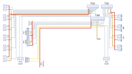
I made a wiring diagram for myself.
You need the PLA button (2 wires). And the PLA sensors wires (2 wires).
In theory all the rest is already there.
Bang on, nice diagram bud here’s the Elsa one if anyone wants it.
View attachment A3 Park assist wiring diagram.pdf
Sent from my iPhone using Tapatalk

Yes from the Elsa diagram I made mine as well.Bang on, nice diagram bud here’s the Elsa one if anyone wants it.
I wanted to visualize the route of the cables!
Ναι Έλληνας
Χάρηκα αδερφέ!Ανδρεας από Λεσβο.
Sorry for the greeklish guys,just saying hi to a fellow Greek.
Sent from my iPhone using Tapatalk
Connectors coming through today. Will be finishing the mod today or tomorrow 

Sent from my ONEPLUS A5010 with Tapatalk


Sent from my ONEPLUS A5010 with Tapatalk
Sooo, I've finished version 1.0 (concept) document of the write-up.
Please, take a quick look at it, if something is not clear I will change it up for the final document of take some better pictures.
Since I'm not finished myself completely I still need to take some pictures of the PLA steps at the end") .
.
Note: since the manual is quite large I needed to compress the file losing some image quality. The final product will be uploaded somewhere seperatly (can only upload max 2MB on this forum).
Please, take a quick look at it, if something is not clear I will change it up for the final document of take some better pictures.
Since I'm not finished myself completely I still need to take some pictures of the PLA steps at the end
.Note: since the manual is quite large I needed to compress the file losing some image quality. The final product will be uploaded somewhere seperatly (can only upload max 2MB on this forum).
Attachments

Amazing guide!
There is a mixup regarding the Centerconsole trim.
Both cars are Facelift. Just have different impementation of the buttons.
Yours witch is a later model, the hole trim and buttons are one unit.
Mine 2010 model (09/2009 build), still facelift, originaly has on the right side of the trim a card holder.
Something like that:

Ofcourse this has to be removed.
Instead there goes a bracket with slots for the 3 buttons. Part number: 8P0941567B (Period: 1008 - 0110 from ETKA)

And then add the two buttons and a blank one.
First slot The blank dummy cover: 8P0941516D,

Second slot the pdc button: 8P0919281,

Third slot the pla button: 8P0927123.

Those two buttons have different connectors (one red and one blue) but don't remember the part number at the moment.
I will post a list of material when finish my build too.
Also for people with no pdc at all, there is needed as well the holder for the module in the trunk (8P4907368).
And offcourse rear sensors, all looms, rear speaker, wiring to the cunbus gateway.
There is a mixup regarding the Centerconsole trim.
Both cars are Facelift. Just have different impementation of the buttons.
Yours witch is a later model, the hole trim and buttons are one unit.
Mine 2010 model (09/2009 build), still facelift, originaly has on the right side of the trim a card holder.
Something like that:
Ofcourse this has to be removed.
Instead there goes a bracket with slots for the 3 buttons. Part number: 8P0941567B (Period: 1008 - 0110 from ETKA)
And then add the two buttons and a blank one.
First slot The blank dummy cover: 8P0941516D,
Second slot the pdc button: 8P0919281,
Third slot the pla button: 8P0927123.
Those two buttons have different connectors (one red and one blue) but don't remember the part number at the moment.
I will post a list of material when finish my build too.
Also for people with no pdc at all, there is needed as well the holder for the module in the trunk (8P4907368).
And offcourse rear sensors, all looms, rear speaker, wiring to the cunbus gateway.
Well, got the cables in today..

I then took the front off and spliced these badboys into the existing PDC loom.
Hence the mess, it's just for testing purposes now.
I made sure PIN 1 of the PDC was connected to PIN 1 of the PLA sensor (live) and PIN 3 on PIN 3 (earth).


The blue wire is PIN 2 (signal) I attached those to the connector on the loom so it's connected to the PDC/PLA module
But unfortunatly is still gives me errors.
First time (after connecting the battery) it only gave me this error, I cleared it and didn't came back.

After that it gave me this error. Which let me think about something in the wiring, but to rule it out I wanted to be sure and swapped sides on sensors (so left to right and right to left).

And hence the problem switched too which make me believe the sensor is at fault
I'm not sure, didn't had enough time to investigate the whole problem this afternoon so I will dig into it deeper tomorrow.

The error it gives is "Open or Short to Ground" which make me believe it can also be the wiring, so I'm once again asking you guys, any ideas?
I want to know, what side of the PLA sensor is PIN 1? because the connectors I got can be plugged in two ways, so PIN 1 and 3 can be switched and I'm not sure. Then again, the left side is error free so that rules out the cable problem I guess... I'm a bit bazzled, hope the system is up and running tomorrow...
Any help appreciated lads
I then took the front off and spliced these badboys into the existing PDC loom.
Hence the mess, it's just for testing purposes now.
I made sure PIN 1 of the PDC was connected to PIN 1 of the PLA sensor (live) and PIN 3 on PIN 3 (earth).
The blue wire is PIN 2 (signal) I attached those to the connector on the loom so it's connected to the PDC/PLA module
But unfortunatly is still gives me errors.
First time (after connecting the battery) it only gave me this error, I cleared it and didn't came back.
After that it gave me this error. Which let me think about something in the wiring, but to rule it out I wanted to be sure and swapped sides on sensors (so left to right and right to left).
And hence the problem switched too which make me believe the sensor is at fault
I'm not sure, didn't had enough time to investigate the whole problem this afternoon so I will dig into it deeper tomorrow.
The error it gives is "Open or Short to Ground" which make me believe it can also be the wiring, so I'm once again asking you guys, any ideas?
I want to know, what side of the PLA sensor is PIN 1? because the connectors I got can be plugged in two ways, so PIN 1 and 3 can be switched and I'm not sure. Then again, the left side is error free so that rules out the cable problem I guess... I'm a bit bazzled, hope the system is up and running tomorrow...
Any help appreciated lads
I found a random picture online when searching for 1T0919297A.

But I also believe that you might have a bad sensor. As you can replicate the problem on either side of the bumper. I hope you find the problem fast.
You can check with a multimeter and the connector disconnected if you can read 12V between Pins 1 and 3.
And then check if there is a voltage drop when you plug the connector to the sensor.
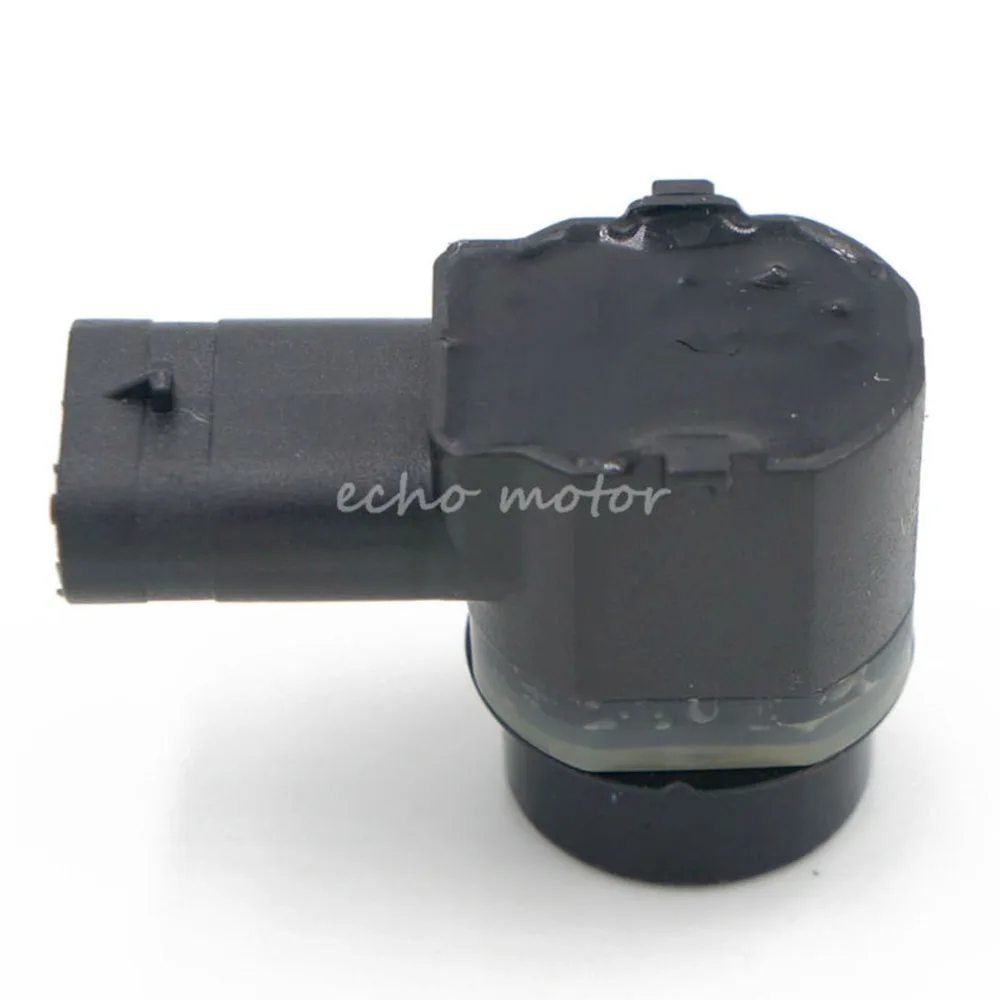
This is a Chinese PLA sensor; https://nl.aliexpress.com/item/32607470916.html?spm=a2g0s.9042311.0.0.7fcd4c4dzBF9E7
As shown in the description the OEM Audi p/n: 1T0919297A


I have two types connector. @Troubs12 told me to purchase the PLA connector 4H0 973 703 A. I've got them but I didnt had the terminals and found some connectors with terminals already in them on Ali so purchased those. Those Ali connectors got the number 4F0 973 703
Almost the same and they don't differ that much.. So I don't think those are the problem? The only difference I see is the locking mechanism and there is a small gap that is on a slight different location. But looking at the PLA sensor there is no "gap" or something that could slide into that "gap".


As shown in the description the OEM Audi p/n: 1T0919297A
I have two types connector. @Troubs12 told me to purchase the PLA connector 4H0 973 703 A. I've got them but I didnt had the terminals and found some connectors with terminals already in them on Ali so purchased those. Those Ali connectors got the number 4F0 973 703
Almost the same and they don't differ that much.. So I don't think those are the problem? The only difference I see is the locking mechanism and there is a small gap that is on a slight different location. But looking at the PLA sensor there is no "gap" or something that could slide into that "gap".
I'm currently pulling all the wires and terminals from the Ali connector and pinning the OEM Audi connector. Don't think it makes a difference but yeah, why not since it's not working now and got 4 spare Ali connectors .

.

Too be fair bud if the faults only on one side it’s probably the sensor. The part number I gave you was from my car and the ones I have installed on my pla sensors. Though to confirm the sensor or wiring swap the left and right pla sensors. If the fault moves to the right it’s the sensor if not it’s wiring. Hit me up if I can help bud 
Sent from my iPhone using Tapatalk

Sent from my iPhone using Tapatalk
Amazing guide!
There is a mixup regarding the Centerconsole trim.
Both cars are Facelift. Just have different impementation of the buttons.
Yours witch is a later model, the hole trim and buttons are one unit.
Mine 2010 model (09/2009 build), still facelift, originaly has on the right side of the trim a card holder.
Something like that:
View attachment 206648
Ofcourse this has to be removed.
Instead there goes a bracket with slots for the 3 buttons. Part number: 8P0941567B (Period: 1008 - 0110 from ETKA)
View attachment 206649
And then add the two buttons and a blank one.
First slot The blank dummy cover: 8P0941516D,
View attachment 206650
Second slot the pdc button: 8P0919281,
View attachment 206652
Third slot the pla button: 8P0927123.
View attachment 206651
Those two buttons have different connectors (one red and one blue) but don't remember the part number at the moment.
I will post a list of material when finish my build too.
Also for people with no pdc at all, there is needed as well the holder for the module in the trunk (8P4907368).
And offcourse rear sensors, all looms, rear speaker, wiring to the cunbus gateway.
Those are what I had to use matey, for the holder in the boot the pdc control unit mounts on to the same bracket that the comfort ecu sits in so it should already be installed on most if not all from factory
Sent from my iPhone using Tapatalk
Asked for a refund on the PLA sensors (bummer because I already painted them.....)
And directly ordered four new ones. Hope they'll do the job then.
And directly ordered four new ones. Hope they'll do the job then.
Asked for a refund on the PLA sensors (bummer because I already painted them.....)
And directly ordered four new ones. Hope they'll do the job then.
Too be honest mate try the new one before paint, I’m sure though when I was at Audi the black parking sensors weren’t painted and just left black. That was definitely the case at VW but I’m not sure about Audi. I painted mine as I had some left over from a mirror cap I had to replace. Did you swap from left to right? If you get no joy with the new one message me I’m sure I’ve got a spare here I can send you. If fact I’m 100% sure I have I think I’ve put pics of it up here lol
Sent from my iPhone using Tapatalk
Yeah I did but want to give it a go one more time tomorrow. Got my hopes upToo be honest mate try the new one before paint, I’m sure though when I was at Audi the black parking sensors weren’t painted and just left black. That was definitely the case at VW but I’m not sure about Audi. I painted mine as I had some left over from a mirror cap I had to replace. Did you swap from left to right? If you get no joy with the new one message me I’m sure I’ve got a spare here I can send you. If fact I’m 100% sure I have I think I’ve put pics of it up here lol
Sent from my iPhone using Tapatalk

Sent from my ONEPLUS A5010 with Tapatalk
Troubs12 I have no comfort ecu either. From some point they merged it to the center electronics if I am not mistaken.Those are what I had to use matey, for the holder in the boot the pdc control unit mounts on to the same bracket that the comfort ecu sits in so it should already be installed on most if not all from factory
The boot is empty at that location!
Attachments

Curious how a PLA sensor looks inside?
I "solved" the issue by putting A PDC sensor in it for the time being. All problems are gone from the module so the wiring is OK.
Next problem: the parkingaid button keeps flashing (stays on). Which is giving me problems in activating/de-activating the PDC. When I put it out reverse gear the system keeps activating because of the centre button that keeps turning on.
Sooooo dive into the internal wiring again today

Sent from my ONEPLUS A5010 with Tapatalk
Well, PLA sensor problem "solved". Now know it's a defect so new ones on their way from China already .
For the time being I placed an spare PDC one in and that cleared the VAGCOM fault.
However, a new one occured, please take a look at the video;
So what you are see happening in the video is this;
1. I put the car on ignition I and the PDC button goes to "on" and is not coming off.
2. I put the car in reverse which triggers the PDC and OPS to display on my RNS-E.
3. Then I put the car in neutral and the OPS doesn't go away from screen, prob because the PDC button is "locked" and won't go off.
4. After ticking the button a few times the rear buzzer gives a long beep, indicating a fault.
5. Then I don't know what is happening, the system isn't working correctly. The beeping of PDC continues while in neutral (I think because of the locked PDC button).
6. I then check VCDS/VAGCOM and indeed it gives me a fault on the button (light). Short to ground.
7. Erasing the fualt doesn't make any difference. However, the system won't work as intended anymore.
And I did some thinking (aaah yes, good old thinking). Kufatec sold the loom as a "PDC" loom. I have a centre trim with PDC and PLA button already in it. My centre trim has those two buttons combined into one connector. So obviously the wires for the PLA button are not in the connector missing out. Maybe the short to ground can be explained by the fact I didn't pin (yet) the PLA connector.. That being said, tomorrow I will be pinnen the PLA button too to check.
Maybe anyone got another idea in what I'm missing? A short to ground means a cable or terminal isn't properly connected. This loom is from Kufatec (and tested). I connected all other ends so I really don't know what it could be else.
.For the time being I placed an spare PDC one in and that cleared the VAGCOM fault.
However, a new one occured
, please take a look at the video;So what you are see happening in the video is this;
1. I put the car on ignition I and the PDC button goes to "on" and is not coming off.
2. I put the car in reverse which triggers the PDC and OPS to display on my RNS-E.
3. Then I put the car in neutral and the OPS doesn't go away from screen, prob because the PDC button is "locked" and won't go off.
4. After ticking the button a few times the rear buzzer gives a long beep, indicating a fault.
5. Then I don't know what is happening, the system isn't working correctly. The beeping of PDC continues while in neutral (I think because of the locked PDC button).
6. I then check VCDS/VAGCOM and indeed it gives me a fault on the button (light). Short to ground.
7. Erasing the fualt doesn't make any difference. However, the system won't work as intended anymore.
And I did some thinking (aaah yes, good old thinking). Kufatec sold the loom as a "PDC" loom. I have a centre trim with PDC and PLA button already in it. My centre trim has those two buttons combined into one connector. So obviously the wires for the PLA button are not in the connector missing out. Maybe the short to ground can be explained by the fact I didn't pin (yet) the PLA connector.. That being said, tomorrow I will be pinnen the PLA button too to check.
Maybe anyone got another idea in what I'm missing? A short to ground means a cable or terminal isn't properly connected. This loom is from Kufatec (and tested). I connected all other ends so I really don't know what it could be else.
Meeeeeeeeeeh kind of out ideas. I couldn't let it sit so I drove to the workplace to wire the connector and..... no change.
I have no ElsaWin so it's a pity for me to see if I forgot any wires. Luckily @Troubs12 posted a few diagrams and so I saw the diagram of the connector in the centre console.
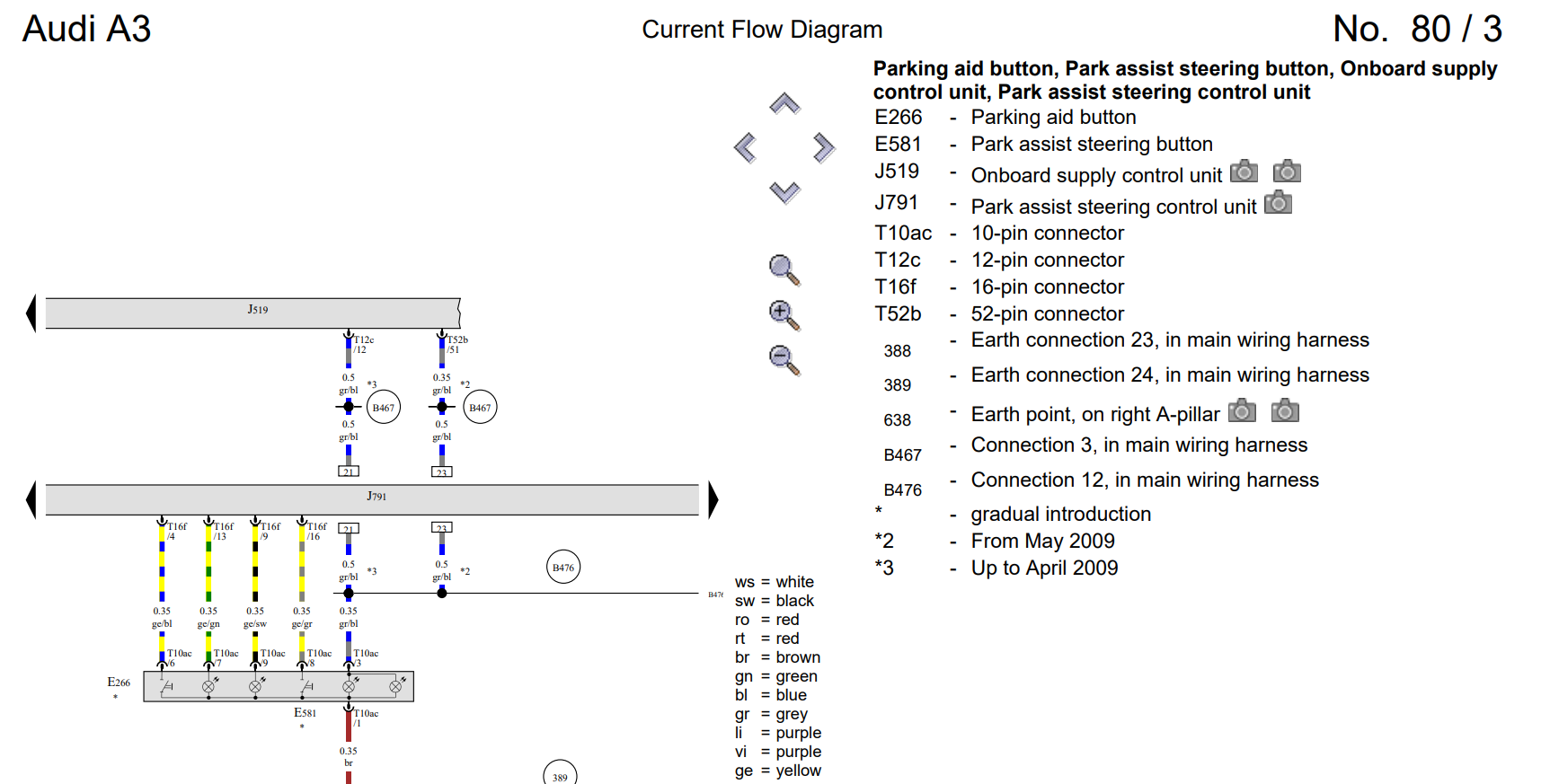
When I opened up the 10PINS centre console connector I saw that the following PINS were used; 1, 3, 6, 7
PIN 6 -> 16 PINS connector (pin 4)
PIN 7 -> 16 PINS connector (pin 13)
PIN 9 -> 16 PINS connector (pin 9)
PIN 8 -> 16 PINS connector (pin 16)
PIN 3 -> BCM connector B (pin 52)
PIN 1 -> Ground


When looking at the diagram above pins; 6 (??), 7 (??), 9 (??), 8 (??), 3 (for the lightning of the buttons) and 1 (ground) should be in "use". So I had two "missing" pins. Those could make sense since Kufatec sells the loom as a PDC loom and not PDC + PLA. So I wired the missing pins 9 and 8 to the T16f/9 and T16f/16. Hoping these pins would "close" a circuit making the PDC button work but unfortunatly those two didn't help. My PLA button is also non-reactive (stays off).
Looking a page further in the Elsa Troubs provided I can see the diagram of the version trim that has two seperate buttons (like George has).
I see in this diagram that the PDC button wires to PIN 16 and PIN 9 on the 16 pins connector of the PDC/PLA module, so I know for sure PIN 8 and 9 on my trim connector are for PDC.
Looking at PDC I see PIN 4 and 13 being used. So I now know PIN 6 and 7 on my connector are for the PDC.
Buttttt, the button is non-reactive, I'm out of ideas..
I have no ElsaWin so it's a pity for me to see if I forgot any wires. Luckily @Troubs12 posted a few diagrams and so I saw the diagram of the connector in the centre console.
When I opened up the 10PINS centre console connector I saw that the following PINS were used; 1, 3, 6, 7
PIN 6 -> 16 PINS connector (pin 4)
PIN 7 -> 16 PINS connector (pin 13)
PIN 9 -> 16 PINS connector (pin 9)
PIN 8 -> 16 PINS connector (pin 16)
PIN 3 -> BCM connector B (pin 52)
PIN 1 -> Ground
When looking at the diagram above pins; 6 (??), 7 (??), 9 (??), 8 (??), 3 (for the lightning of the buttons) and 1 (ground) should be in "use". So I had two "missing" pins. Those could make sense since Kufatec sells the loom as a PDC loom and not PDC + PLA. So I wired the missing pins 9 and 8 to the T16f/9 and T16f/16. Hoping these pins would "close" a circuit making the PDC button work but unfortunatly those two didn't help. My PLA button is also non-reactive (stays off).
Looking a page further in the Elsa Troubs provided I can see the diagram of the version trim that has two seperate buttons (like George has).
I see in this diagram that the PDC button wires to PIN 16 and PIN 9 on the 16 pins connector of the PDC/PLA module, so I know for sure PIN 8 and 9 on my trim connector are for PDC.
Looking at PDC I see PIN 4 and 13 being used. So I now know PIN 6 and 7 on my connector are for the PDC.
Buttttt, the button is non-reactive, I'm out of ideas..
Last edited:
You are probably right if the loom is sold for PDC only.
I suppose you are missing 2 wires.
The buttons connector should have 4 wires coming from the Module T16f connector.
On the T16f connector on the module,
Pin 4 parking aid button (pin 6 on Trim connector)
Pin 9 park assist steering button led (pin 9 on Trim connector)
Pin 13 parking aid button led (pin 7 on Trim connector)
Pin 16 park assist steering button (pin 8 on Trim connector)
So I suppose you are missing cables on Pin 9 and 16 maybe.
You can check the T16f connector on the module.
The attachment is for your kind of Trim with the combined connector.
Attachments

You got me first.
You can also check if the two cables for the PDC button go in the correct positions. They might be mixed? (But I don't think so).
Pin 6 -> T16f/4
Pin 7 -> T16f/13
Also pin 3 is 12V for illumination, pin 1 is ground.
If you check the previous attachment, pin 3 must go on T52b/51.
Not pin 52 that you wrote before.
You can also check this.
Actually are the buttons light when you turn on the lights?
You got me first.
You can also check if the two cables for the PDC button go in the correct positions. They might be mixed? (But I don't think so).
Pin 6 -> T16f/4
Pin 7 -> T16f/13
Also pin 3 is 12V for illumination, pin 1 is ground.
If you check the previous attachment, pin 3 must go on T52b/51.
Not pin 52 that you wrote before.
You can also check this.
Actually are the buttons light when you turn on the lights?
Yep the buttons light up (also with my old 4K PDC module.
When I attach my old 4K module the button won't work but the light will turn up. I think this is due to the fact the 12V for illumination of the buttons is a seperate line to the BCM instead of the parking module. Als the ground is attached under the A-pillar.
So the "problem" should be in those wires I guess, otherwise I think my module is at fault? I can't believe that since the PDC works but it doesn't turn off because of the button grrrrrrrrr
Can you check the 2 (old) wires for continuity with a multimeter?
Check that Pin 6 goes in fact on T16f/4 and pin 7 goes in fact on T16f/13.
Actually you can test this with a simple test. If you unplug pin T16f/13 (parking aid button led) from the module, and check the PDC button led. It should not light up any more.
Check that Pin 6 goes in fact on T16f/4 and pin 7 goes in fact on T16f/13.
Actually you can test this with a simple test. If you unplug pin T16f/13 (parking aid button led) from the module, and check the PDC button led. It should not light up any more.
Can you check the 2 (old) wires for continuity with a multimeter?
Check that Pin 6 goes in fact on T16f/4 and pin 7 goes in fact on T16f/13.
Actually you can test this with a simple test. If you unplug pin T16f/13 (parking aid button led) from the module, and check the PDC button led. It should not light up any more.
I will check this first thing tomorrow, thanks mate!
Troubs12 I have no comfort ecu either. From some point they merged it to the center electronics if I am not mistaken.
The boot is empty at that location!
Ahhhhh yeah from 2009 ish they put the comfort ecu inside the central electrics ecu my bad buddy
Sent from my iPhone using Tapatalk

Aaaaand Kufatec had the imprints on their cable printed wrong. Switched PIN 13 and 4 and the system works  .
.
Today @Troubs12 helped me coding the PLA in the dash and wiring the button. After the PLA turns on but throws an "system error". When reading with VCDS no error can be found.
The fact the system works and is wired correctly my guess is the PDC sensor that works as a PLA now is the issue. So the waiting game for the right PLA sensor begins...
Happy the system works though, enjoying front and rear PDC for the time being.
Thanks all!!!

Sent from my ONEPLUS A5010 with Tapatalk

 .
.Today @Troubs12 helped me coding the PLA in the dash and wiring the button. After the PLA turns on but throws an "system error". When reading with VCDS no error can be found.
The fact the system works and is wired correctly my guess is the PDC sensor that works as a PLA now is the issue. So the waiting game for the right PLA sensor begins...
Happy the system works though, enjoying front and rear PDC for the time being.
Thanks all!!!

Sent from my ONEPLUS A5010 with Tapatalk

Last edited:
Glad you found it!
I hope with the new PL A sensor all your problems end!
I hope with the new PL A sensor all your problems end!
Hey the document request access authorization. it is not public..
Woooops, and this one? (CLICK)
URL: https://drive.google.com/file/d/1swecYXj-KSaVhiRgSmx6YdqBy_7jCApv/view?usp=sharing
Since I don't have much to do (vacation untill 1st of August) I made a version 3.0 already .
Much shorter and clearer and better for people who also want to fit this. If you see any faults or have suggestions, don't hesitate to hit me up.
Download from Google Drive: CLICK
https://drive.google.com/file/d/1RXyn9WbqHW3N8i-eYPQ8eGeaP4S3ssw0/view?usp=sharing
.Much shorter and clearer and better for people who also want to fit this. If you see any faults or have suggestions, don't hesitate to hit me up.
Download from Google Drive: CLICK
https://drive.google.com/file/d/1RXyn9WbqHW3N8i-eYPQ8eGeaP4S3ssw0/view?usp=sharing
Some sad but good news.
Yesterday a random fault popped up in the PDC module, seems like a sensor is at fault causing a short-to-ground.
Took the front end off today since I wanted to tape the loom and check this issue out. After a small hour of testing I came to the conclusion the other PLA sensor died aswell....
Luckily for me I had two spare PDC sensors and fit the PLA brackets. So those are in for the moment. After fitting those I had no fault codes anymore. I drove the car out and pressed the PLA button, it stayed on and waited for a free parking spot... I directly tested the function I it works!!! I'm guessing both PLA sensors died during the painting, a bummer but got a refund from China so all sorted lol.