

PFL to FL Dynamic Taillights conversion guide
- Thread starter larbel
- Start date
You are using an out of date browser. It may not display this or other websites correctly.
You should upgrade or use an alternative browser.
You should upgrade or use an alternative browser.
Grattamone
Registered User
@larbel, you were right.
I've figured out that NAR codes were
8V4 954 091A
8V4 954 093E
8V4 954 094E
8V4 954 092A
European's are
8V4 954 091
8V4 954 093C
8V4 954 094C
8V4 954 092
I've made some testing with a 9V battery and the turning signal came together with the brake signal.
I'm dying
I'm now good for a refund.
I've figured out that NAR codes were
8V4 954 091A
8V4 954 093E
8V4 954 094E
8V4 954 092A
European's are
8V4 954 091
8V4 954 093C
8V4 954 094C
8V4 954 092
I've made some testing with a 9V battery and the turning signal came together with the brake signal.
I'm dying
I'm now good for a refund.
@larbel, you were right.
I've figured out that NAR codes were
8V4 954 091A
8V4 954 093E
8V4 954 094E
8V4 954 092A
European's are
8V4 954 091
8V4 954 093C
8V4 954 094C
8V4 954 092
I've made some testing with a 9V battery and the turning signal came together with the brake signal.
I'm dying
I'm now good for a refund.
How much you paid for them? PM me if you need help finding the SB lights...
Grattamone
Registered User
190€ each, but still ok for a refund.
Bought the new ones on ebay this morning. Thank you larbel.
Bought the new ones on ebay this morning. Thank you larbel.
Wooyong Lee
Registered User
Hello All
I have a3 8V North-America ver.
I did this instruction PFL -> PL, but the dynamic turning signals work with brake light
Anyone can solve this problem?
Thanks in advance

I have a3 8V North-America ver.
I did this instruction PFL -> PL, but the dynamic turning signals work with brake light
Anyone can solve this problem?
Thanks in advance
Last edited:
dannyboy1985
Registered User
Hello All
I have a3 8V North-America ver.
I did this instruction PFL -> PL, but the dynamic turning signals work with brake light
Anyone can solve this problem?
Thanks in advance
View attachment 171942
I think the only way to change it is purchasing the Europe model lights not us. Lots of tails in the states use red as indicators where as Europe it’s just yellow.
Wooyong Lee
Registered User
I think the only way to change it is purchasing the Europe model lights not us. Lots of tails in the states use red as indicators where as Europe it’s just yellow.
I have EU ver
")
upper dynamic light is yellow and brake light is red but work together now
dannyboy1985
Registered User
I have EU ver
upper dynamic light is yellow and brake light is red but work together now
You followed the Audizine guide on wiring right? As far as I know, there's two things that need to be happened.. The NAR outer tail has one wire for both turn signal and brakes, you'll need to run a turn signal wire from the inner light to the outer for turn signal. And then with VCDS/OBD11, you'll need to disable the NAR function from presumably Adaptations... Pretty sure I asked on Audizine if anyone can provide the NAR version of J519's number to verify if it's the same as EU or can check on ETKA the functions, but don't think anyone ever came forwarded...

Wooyong Lee
Registered User
thank you all !Woo-
If you do a scan of your 09 module I can help you with the coding to see if that is correct.
i have obd cable, but i never use that
how can i scan 09 module ?
everything working good without that (turn light working with brake light)
Wooyong Lee
Registered User
thank you all !
i have obd cable, but i never use that
how can i scan 09 module ?
everything working good without that (turn light working with brake light)
I got some information from google about 09 module, i understood central elec., but I can't find about brake light and turn light
Anyone have coding infor. ?
Thanks in advance
dannyboy1985
Registered User
DJAlix
VAG CAR CODING
Site Sponsor
VCDS Map User
VAG Can Professional
ODIS (Offboard Diagnostic System)

dannyboy1985
Registered User
Its my turn for tail lights conversion
I have collected all connectors nedded and waiting the dynamic lights from DPD....
Happy Days!
I got some information from google about 09 module, i understood central elec., but I can't find about brake light and turn light
Anyone have coding infor. ?
Thanks in advance
Can you send me your 09 adaptation map? You will need to retrieve it once it is saved.
I recently did the PFL to FL dynamic taillights conversion with self made wiring loom, someone was asking me the details so I figured I'll just make a post for it.
First of all, here's the pinouts for the FL dynamic taillights (This is same for SB/Sedan)
Outer Lamp (Same for left and right side)
Pin 1 - Ground
Pin 2 - Tail lamp
Pin 3 - Brake lamp
Pin 4 - Turn signal lamp
Pin 5 - Dynamic control - This is the wire that needs to tap to live power
Pin 6 - Tail lamp 2 (connected to inner lamp's running lamp)
Inner Lamp (Same for left and right side)
Pin 1 - Ground
Pin 2 - Tail lamp
Pin 3 - Turn signal lamp
Pin 4 - Fog lamp
Pin 5 - Reverse lamp
Pin 6 - Dynamic control - This is the wire that needs to tap to live power
On the PFL, there's only 5 wires each for the inner and outer lamps, but on the FL dynamic, there's 6 wires each, the additional wire (in red above) is the power for the dynamic module inside the tail lamp, without this wire, everything will still functions normally, just without the dynamic sweeping function.
The FL dynamic taillights has different housing for SB and Sedan, but the connectors and pinouts are identical. On the PFL taillights, SB and Sedan shares the same OUTER lamp connector, but the INNER lamp connectors are different, SB has 8 pins connector while Sedan uses 5 pins connector.
And here's the wiring diagram for PFL SB:
View attachment 129244 View attachment 129245
And here's the wiring diagram for PFL Sedan:
View attachment 129247 View attachment 129249 View attachment 129250
Outer Lamps:
The connector for both SB/Sedan's OUTER lamp needed is this (Part number 4H0 973 713 C): (** Some PFL SB came standard with this connector for the outer taillight already, so check first)
View attachment 129243
The outer lamp for both SB and Sedan is pretty straight forward, all you need to do is re-pin the wires to this connector using the PFL to FL pinouts above. You can remove the wires by unlocking the purple lock tab inside the connector by sliding it out to the open slot using a screwdriver, and the best way to loosen up the pin locks are by using Molex pin extractor OR two iPhone SIM card removal pins, works like a charm
Inner Lamps:
Here's where the original PFL connectors are different for SB and Sedan, but both need this connector to connect to the FL taillight connector (Part number 4B0 971 636):
View attachment 129253
For Sedan, this is the 5 pins male connector I also ordered since I didn't want to cut any wire (Part number 5G0 972 715) and the wiring loom I made using these connectors for my Sedan:
View attachment 129254 View attachment 129255
The extra yellow wire on my wiring loom is the inner lamp's control wire.
For Sportback, I do NOT have the male connector's part number, but this is what the PFL 8 pins looks like, you can check it's part number and should easily find it's counterpart online:
View attachment 129256
Once you have the wiring loom made according to the pinouts above and connected them up, run the control wire to the left side of the trunk (Coz the fuse box is on the left side), connect all four control wires into one and run it to the fuse box in the glove compartment, I used fuse F38 for constant power like this (borrowed from Blackvue install thread
View attachment 129260
The taillight cost about £600 from my supplier, the connectors etc another £50 or so, but my original taillight were sold for £300 so this whole project cost me about £350
*** Depends on how anal you are, you don't really have to use any connectors at all, you can opt to just remove the pins from the original connector and isolate them with heat shrink then plug them directly into the FL taillights and seal it with hotmelt or something, like these guys...
View attachment 129261 View attachment 129262
**** Also the FL taillights' plastic trims are different, you can still use the PFL ones but it's not a perfect fit, I ordered FL ones for my Sedan since they're only like $30 total or so, here're the part numbers for Sedan:
8V5 945 253 B
8V5 945 254 B
8V5 945 255 B
8V5 945 256 B
***** I wrote this quick and based on the assumption that the person chose to do this have the basic knowledge of reading the pinouts and tearing down the car, I would not be held responsible for any damage done following this guide, proceed at your own risk, but of course, I'll be happy to answer any questions if there's any
And here's the result:
I have one question:
Old tail lights have bulbs for fog & reverse lights. New tailtlightshave leds. After light installation is there any fault bulb warning message at instrument cluster?
Sorry for bringing up a old thread do you have the vcds code to map out the bulb out errors
I have pfl led tail lights and i want to install fl led tail lights.
Vcds needs for normal tail lights with bulbs?

I have upgraded mine but getting bulb out errors so need the vcds coding to map them out, i see alot of people asking but get no replyI have pfl led tail lights and i want to install fl led tail lights.
Vcds needs for normal tail lights with bulbs?
dannyboy1985
Registered User
I have.... Got bulb out errors I need to code outYou only need to code if going halogen to led.

Thanks mateYou only need to code if going halogen to led.

I just made a quick test and remove reverse kight bulb and warning message came into cluster for burn bulb. I guess the FL full led lights have resistors for fog and reverse leds...Thanks mate

dannyboy1985
Registered User
I just made a quick test and remove reverse kight bulb and warning message came into cluster for burn bulb. I guess the FL full led lights have resistors for fog and reverse leds...
Yes, even on a halogen car with no coding the led lights don’t show warnings on the dash.
This sound good.Yes, even on a halogen car with no coding the led lights don’t show warnings on the dash.
I have PFL leds now and i am happy because dont need codding to seperate the tail light from stop signal , after FL installation
PFL Sportback to FL Dynamic light plug pin wiring
I would just like to point out that there are several posts on the net stating you will need to purchase semi dynamic modules from places like K Electronics to complete the job, this is not the case there is no coding necessary either!
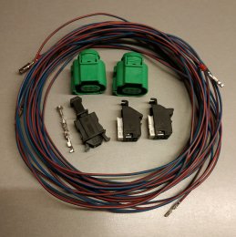
Parts Needed to complete the upgrade.
New set of 2017 dynamic lights
Inner plugs x 2
Repair cables x 6
Single core cable x 10m
Inline fuse x 1
As with any project, please test each function of every wire before soldering/fitting to plugs as some models may differ, I will not be held responsible for any mishaps/damage to fittings fixtures.
Outer Lamp Left
Pin 1 – Ground Brown
Pin 2 - Tail lamp Blue/White and Brown/Red connected together
Pin 3 - Brake lamp Blue
Pin 4 - Turn signal lamp Blue/Yellow
Pin 5 - live power Needed to make dynamic indicator work
Pin 6 – Not used
Inner Lamp Left
Pin 1 – Ground Brown
Pin 2 - Tail lamp Brown/Red
Pin 3 - Turn signal lamp Grey
Pin 4 - Fog lamp Red/White
Pin 5 - Reverse lamp Black/Blue
Pin 6 - live power Needed to make dynamic indicator work
Outer Lamp Right
Pin 1 – Ground Brown
Pin 2 - Tail lamp Red/Green and Brown/Yellow connected together
Pin 3 - Brake lamp Green/Brown
Pin 4 - Turn signal lamp Mauve
Pin 5 - live power Needed to make dynamic indicator work
Pin 6 – Not used
Inner Lamp Right
Pin 1 – Ground Brown
Pin 2 - Tail lamp Brown/Yellow
Pin 3 - Turn signal lamp Brown/Red
Pin 4 - Fog lamp Green/Yellow
Pin 5 - Reverse lamp Green/Red
Pin 6 - live power Needed to make dynamic indicator work
Outer Lamps
The original outer lamp plug will fit on the new lamp socket but will need a small locating pin removing first from the new socket first, I used a dremmel but a stanley knife would suffice, and would then need repining as per the above chart.
Inner Lamps
The inner lamps will need the original plugs removing and new connectors fitting (part number 4B0 971 636), I would recommend using repair wires as the pins are very small and fiddley, sorry not sure on the part number, but when I purchased the plugs I asked for the repair leads to fit at the same time. You will need three for each side, these will need soldering in place as per the chart above.
Installation is the same as written in larbel’s sedan post, I didn’t take any pictures for the conversion as I wasn’t going to write a guide, but then thought afterwards that I should share my findings
Hello my friend
I have done the tail light swap acording your diagram. I have one problem:
When ignition is OFF dynamic turn signals work fine
When engine is running the dynamic turn signals dont work well.
Start with dynamic, after 3 flashes work like semi dymanic and after 3 flashes work normal . Dont know what to think.
There is not any fault code with vcds.
Any idea?
PFL Sportback to FL Dynamic light plug pin wiring
I would just like to point out that there are several posts on the net stating you will need to purchase semi dynamic modules from places like K Electronics to complete the job, this is not the case there is no coding necessary either!
Parts Needed to complete the upgrade.
New set of 2017 dynamic lights
Inner plugs x 2
Repair cables x 6
Single core cable x 10m
Inline fuse x 1
As with any project, please test each function of every wire before soldering/fitting to plugs as some models may differ, I will not be held responsible for any mishaps/damage to fittings fixtures.
Outer Lamp Left
Pin 1 – Ground Brown
Pin 2 - Tail lamp Blue/White and Brown/Red connected together
Pin 3 - Brake lamp Blue
Pin 4 - Turn signal lamp Blue/Yellow
Pin 5 - live power Needed to make dynamic indicator work
Pin 6 – Not used
Inner Lamp Left
Pin 1 – Ground Brown
Pin 2 - Tail lamp Brown/Red
Pin 3 - Turn signal lamp Grey
Pin 4 - Fog lamp Red/White
Pin 5 - Reverse lamp Black/Blue
Pin 6 - live power Needed to make dynamic indicator work
Outer Lamp Right
Pin 1 – Ground Brown
Pin 2 - Tail lamp Red/Green and Brown/Yellow connected together
Pin 3 - Brake lamp Green/Brown
Pin 4 - Turn signal lamp Mauve
Pin 5 - live power Needed to make dynamic indicator work
Pin 6 – Not used
Inner Lamp Right
Pin 1 – Ground Brown
Pin 2 - Tail lamp Brown/Yellow
Pin 3 - Turn signal lamp Brown/Red
Pin 4 - Fog lamp Green/Yellow
Pin 5 - Reverse lamp Green/Red
Pin 6 - live power Needed to make dynamic indicator work
Outer Lamps
The original outer lamp plug will fit on the new lamp socket but will need a small locating pin removing first from the new socket first, I used a dremmel but a stanley knife would suffice, and would then need repining as per the above chart.
Inner Lamps
The inner lamps will need the original plugs removing and new connectors fitting (part number 4B0 971 636), I would recommend using repair wires as the pins are very small and fiddley, sorry not sure on the part number, but when I purchased the plugs I asked for the repair leads to fit at the same time. You will need three for each side, these will need soldering in place as per the chart above.
Installation is the same as written in larbel’s sedan post, I didn’t take any pictures for the conversion as I wasn’t going to write a guide, but then thought afterwards that I should share my findings
Hello my friend
I have done the tail light swap acording your diagram. I have one problem:
When ignition is OFF dynamic turn signals work fine
When engine is running the dynamic turn signals dont work well.
Start with dynamic, after 3 flashes work like semi dymanic and after 3 flashes work normal . Dont know what to think.
There is not any fault code with vcds.
Any idea?
Do you have constant power to the dynamic module? Are you using an adapter to convert power? What happens when the engine is running is the voltage in the system goes higher than 12v. If you have to run the blinker to the outer tail you may also need some energy storage to that the signal can drive the LEDs
Last edited:
DJAlix
VAG CAR CODING
Site Sponsor
VCDS Map User
VAG Can Professional
ODIS (Offboard Diagnostic System)
Anyone can help;
After tail light swap with engine running the dymanic is confused!!!!!
Without engine running everything work fine.

If you can get to me in north London I can resolve this issue.
dannyboy1985
Registered User
Hello my friend
I have done the tail light swap acording your diagram. I have one problem:
When ignition is OFF dynamic turn signals work fine
When engine is running the dynamic turn signals dont work well.
Start with dynamic, after 3 flashes work like semi dymanic and after 3 flashes work normal . Dont know what to think.
There is not any fault code with vcds.
Any idea?
Mine seems to work fine but I would guess as already stated it’s to do with the voltage going to the dynamic modules. Could need a voltage adjuster to keep it down to just 12v. Where have you got the power from?
Mine seems to work fine but I would guess as already stated it’s to do with the voltage going to the dynamic modules. Could need a voltage adjuster to keep it down to just 12v. Where have you got the power from?
Maybe you have right my friend
I got power from battery and i try also from fuse box with same results.
When engine is not running dynamic is perfect because voltage is 12,6 volt.
When engine running voltage is 14 volt amd this is the reason i guess.
From which place i have to take 12v?
dannyboy1985
Registered User
Maybe you have right my friend
I got power from battery and i try also from fuse box with same results.
When engine is not running dynamic is perfect because voltage is 12,6 volt.
When engine running voltage is 14 volt amd this is the reason i guess.
From which place i have to take 12v?
I took mine from the 12v supply in the boot. I’m guessing this may be more regulated than off the battery. That’s why mine works better.. I have just let it run for awhile and it does eventually get out of sync. I have ordered a DC-DC buck converter so will report back once I’ve tried it but I’m sure that’s the issue. Just check the popular auction site they are about £2
I just try with multimeterI took mine from the 12v supply in the boot. I’m guessing this may be more regulated than off the battery. That’s why mine works better.. I have just let it run for awhile and it does eventually get out of sync. I have ordered a DC-DC buck converter so will report back once I’ve tried it but I’m sure that’s the issue. Just check the popular auction site they are about £2
When engine off ---> 12,4 volt
When engine runnimg --->14,6 volt
This cause the problem?
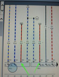
After 3 days into my garage, working with tail lights swap, many tests i found the solution to my problem.
Acording to FL dynamic diagram the outer connector PIN 6 must be connected with inner connector PIN 3 ( this connection cynchonise the dynamic to tail lights). The factory pin 6 from outer black connector soldered with tail light pin 2 like Dannyboy1985
Happy and proud
Acording to FL dynamic diagram the outer connector PIN 6 must be connected with inner connector PIN 3 ( this connection cynchonise the dynamic to tail lights). The factory pin 6 from outer black connector soldered with tail light pin 2 like Dannyboy1985
Happy and proud
Attachments
dannyboy1985
Registered User
Brilliant work I don’t think anyone has solved this and posted it... I can’t believe I missed that looking at the diagram. Will test this weekend and add it to the guide!