Cam cover breather and oil filter housing breather meet at t-joint, go in to catch can. Then from the catch can into hockey puck into TIP.That depends, how did you fit it exactly?
Last edited:
Cam cover breather and oil filter housing breather meet at t-joint, go in to catch can. Then from the catch can into hockey puck into TIP.That depends, how did you fit it exactly?
I’ve been emptying mine once a week since installing it, only ever half full but mostly water with some yellow gunk. Mines not baffled but has some filtration on the outlet of the inside of the catch can.Ill have to have a look in mine and see what's in it. I haven't emptied it since it was put in. I have just been looking in the plastic veiwing tube and it's empty.

I’ve been reading and it’s pretty normal, the water comes from the blow-by when the bang happens water is produced and this condenses in the catch can. Made worst in the cold weather and if you make short journeys.that's what I get out of mine its just yellow emulsified gloop and water - I cannot trust the clear tube for a level, as it gets blocked up straight away.
I hope it’s not filling up too quick, sense says that’s a sign of worn piston rings (excessive blow-by). I’ve routed mine back into the TIP, I don’t know about yours, but it could be sucking it through and filling it up quicker.Sounds like ill need to get mine of and see whats in mine. Hopefully not what use two have been getting in urs.
Is that not a bad sign if its filling up that quick and with the yellow gunk and watery stuff?


Would you tel me any good catch can to use? I read that i need baffled one, but i can't find one with 19mm inlet/outlet.
Could be why your not filling up so much........ I hopeI vented to atmosphere
I’ve got the one SHUk has suggested above. Good solid construction, very well made. But you have to check it at least once a week as there’s no way to tell when it’s full.Would you tel me any good catch can to use? I read that i need baffled one, but i can't find one with 19mm inlet/outlet.
The one I have is so easy to empty as it’s like a jam jar. It’s mounted with a bracket on the lid and the jar just unscrews from the lid, simples. I’ve mounted mine on the battery holder so easier to access than at the back of the engine bay. Only downside is there’s no way knowing how full it is other than opening it. And there’s no real baffle inside, just a semi circular filter, not the best but seems to do the job. I may put some wire wool in to see if that helps.I got a chrome one fits nicely but not baffled so pointless and the only way of emptying it without removing it is by removing the gauge connectors and teasing the gloop out. all show and no go...

That looks like a PITA to empty. But nice mounting spot. I would recommend the one I have, in the eBay link above. I’m worried about how often I have to empty mine and the smoke coming from the exhaust when in boost. I’m not sure the 2 are linked but I’m sure it only started happening after I fitted the catch can.
 and a crap ECU from eBay which was maybe knocking? - everytime I put my foot down I visualise Ian's rods
 What power did he duck them up at? Extra long stroke ftw ha!!I know some people added a valve to try and keep negative pressure in the block and also I am unsure about my puck being straight in the TIP. but my engine puffs out of both the breathers and has done for about a year now (3000 miles) I don't think this was caused by the catch can and was probably from 7000 rpm
View attachment 143246
I have edited as many of the pics as I could on the first page... you should be able to see them now... (although for how long depends on how quickly photobucket catch on)please can someone take a pic 9f their 1.8 turbo agu and show me where catch can goes and where pipes run to .. using thumbnails on here as i don't have photobucket )can't afford it) or any 3rd party way of seeing pics
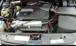
my engine bay is pictured below .. seems different to everyone else's on here
I have edited as many of the pics as I could on the first page... you should be able to see them now... (although for how long depends on how quickly photobucket catch on)
Your engine bay is exactly the same as any other AGU engine bay... its just that everyone else's has been modified so look different
<tuffty/>
I suspect you are referring to an S3 then... they are a slightly different layout to the A3oh!! lol .. all the pics 8 see have a weirdly small cover and hoses etc on top of engine not off to side like mine etc .. my bad
and thanks man .. you're a f...g legend
yeah I take it that's what is in pictures as i can't work out where some of the hoses go to or come from on your pics .. cos they're not in same position as mine .. plus I don't have that silicone hose replacement you guys do .. mines factory pos pipeI suspect you are referring to an S3 then... they are a slightly different layout to the A3
<tuffty/>
basic principles of the PCV delete is the same across all 1.8t's... the main difference is the pipework on the inlet...
<tuffty/>
You need 2-3m of 19mm oil hose, one pipe comes up from oil breather up towards crank case breather with a t piece on connect the abov two and send theirs to catch can, take other side of catch can up to inlet hockey puck. Simples =[]
Edit; You posted pics while I was replying, nice one.
Most of the lines you've highlighted aren't really the PCV system which folk fit the can to.
There's a breather from the crankcase (under the inlet mani), and another from the valve cover (RHS of head once you remove cover). Pull those out, route into a can then on to the TIP from there. Remove any redundant hoses, cap off where they join other systems (brake booster, EVAP if not removing it) and you're done.