In addition to my post above...Looks like the wiring is the same for 2012/13 onwards
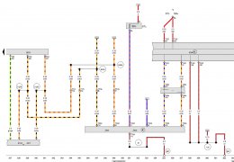
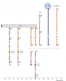
Data bus diagnostic interface
J234 - Airbag control unit
J519 - Onboard supply control unit
J533 - Data bus diagnostic interface
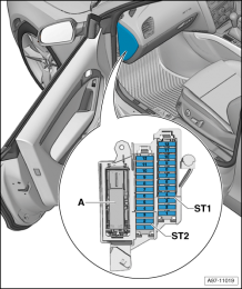
ST1 - Fuse carrier 1
ST2 - Fuse carrier 2
SD7 - Fuse 7 on fuse holder D
SD11 - Fuse 11 on fuse holder D
T16 - 16-pin connector
T16b - 16-pin connector
T17b - 17-pin connector, blue
T17e - 17-pin connector, red
T20d - 20-pin connector
T100 - 100-pin connector
135 - Earth connection 2, in dash panel wiring harness
687 - Earth point 1, on centre tunnel
B383 - Connection 1 (powertrain CAN bus, high), in main wiring harness
B390 - Connection 1 (powertrain CAN bus, low), in main wiring harness
* - see applicable current flow diagram for airbag
*2 - see applicable current flow diagram for fuse assignment
*3 - see applicable current flow diagram for basic equipment
*4 - Diagnostic connection
So agreeing with desertstorm above.
Fuse 7 on Fuse holder 1
Fuse 11 on Fuse holder 2
Pictured the fuse diagrams too.
Should be a handy mod for people to do and saves against buying a OBD protector. As even if the thieves tool can bridge the Terminal 30 and Terminal 15 supplies to link the ignition live, its still not going to work as port is completely dead.


")