Ok as promised here are my pics.
Firstly here's my diagram again so you can follow it with the pics:
Here's the can with it's in/out hose:
The top hose comes down under the TIP and joins to a t-piece. This then goes up to the rocker cover and off to the 90 degree pipe on the oil filer housing. Here you can see the rocker cover route:
Here is a close up of the T-piece taken from the left side of the battery:
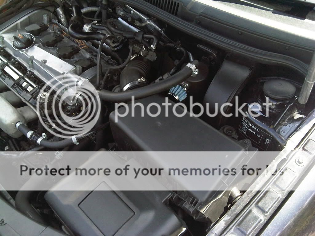
You cant see the hose from the top of the can in these pics but the red line shows the hose to the rocker cover and the blue line shows the hose off to the oil filter:
Here is where it joins the 90 degree bend on the oil filter housing below the inlet mani:
So that's the top pipe on the diagram done. The side pipe out of the can goes down and into the hockey puck which then vents into the TIP as shown here:
Red line shows the hose coming from the side of the can, hockey puck is obvious, the blue line is heading to the TIP and the green line is the TIP:
With all that done that's the hard part. The easy bit is to block off the hose on the bottom of the inlet manifold:
All I did was cut a piece of hose and jubalee clipped in a bolt like so (pic taken through the gap of the inlet mani):
Last thing to do is to sort out the hose that runs off the left hand side of the inlet mani that runs to the break servo:
Now the silver bit in between the 2 90 degree silicone is the 1 way valve which ensures you have servo'd brakes. The hose then just runs up to the hard pipe along the firewall. Not the hose with ASH on it but the one to the right of it:
Now obviously I bought spanking new pipes for the brake servo bit but you can just re use most of the stuff you ripped out and the 1 way valve that was already there. The original 1 way valve was a T-piece 1 way valve so you will need to block off the bottom of the T as described earlier in this thread.
I hope these pics and this explaination help you out, it's really not as daunting as it first seems.


")