- Joined
- Feb 4, 2016
- Messages
- 2,056
- Reaction score
- 734
- Points
- 113
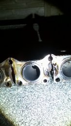
What exhaust manifold do you have, apparently the one of BEX engine is larger.
Sent from my iPhone using Tapatalk
Sent from my iPhone using Tapatalk


I am studying this now and found a few good websites that seem to make sense and go in to a bit of detail.
They cover head porting and port matching from head to manifold and collectors. The main thing they say is that most modern heads and manifold can flow enough volume wise and that the flow with regards to velocity and pressure of the whole system is achieved by removing seems, rough spots, maybe some bumps, smoothing short radii and surface finish to name a few technical steps that can be employed. The shape of the port is far more important that the size to aid flow and most times only the floor or roof of the port is touched and the other surface and walls are untouched. They say that removing to much material kills the flow and velocity of the gas's.

There's a whining noise coming from the rear right wheel arch. This was at a rough idle and the whine went and the idle smoothed out a bit once I cleared the fault codes. The clearing of fault codes resets the fuel trims which might smooth out the idle but why would the whine noise disappear. Also would this whine be part of the evap system or the fuel pump? Starting to think the ECU may be duff after all.
Thanks.
Yes, it was. Sitting about 1200-1300 rpm then dropping way down to 550-600 rpm.
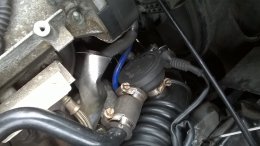
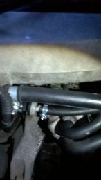
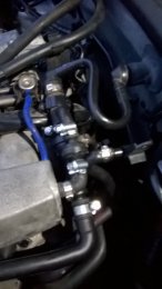
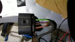
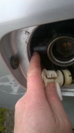
The hose from manifold to FPR looks bad. I'll change it and the drivers side wing gets wild hot were the wiring/hosing from the N80 valve goes in to it. I'll check that out to and the charcoal canister as the tank airlocks while putting fuel in. The nozzle clicks off. Wee bit still to do then.
 this will be the third in 11 years of 1.8t ownership.
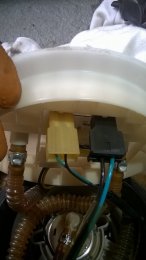
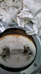
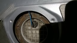
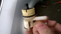
I tested the old pump in a bucket of water and it flows and returns with no problems yet in the car it had no flow with the same power applied. This supports my theory of pump starvation within the reservoir.
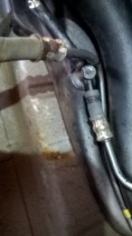
The wiring at the other device at the other side of the car doesn't seem to be doing anything, no ground, no voltage. I will have to try to trace it back and see what the crack is with it.
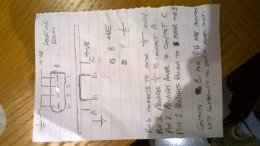
I checked all the connections and made a circuit diagram.
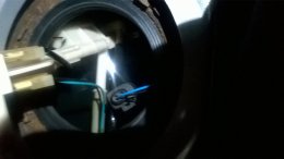
I checked the wires and connections for pin two and three of the fuel pump loom. The ground or chassis -ve is good and the voltage supply to pins two and three is 3.9 volts with a volt drop of 1.3 volts.
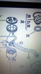
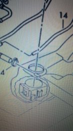
I'm having trouble accessing the wiring diagrams to see where abouts the purple with black returns to so it may have to be a carpet up job, all in the name of motoring I suppose.
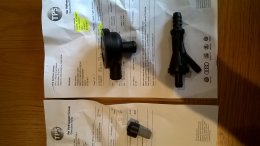
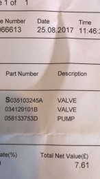
Has anyone tried the N75 valves off of the bay? They are about £27. The ones from tps are about a ton which I need to direct elsewhere. Thanks.