Stacey's Belated Yo Yo Build Thread

Yeh sorry, the hardpipe on an A3 is the main coolant return to the pump. The A4 has a second one which feeds the radiator.

I've no idea what that little pipe does, like i say not that familiar with the A3 engine. Seems odd that it would connect directly to the coolant return though, surely on a standard car thats just going to limit coolant flow thru the matrix and oil cooler by providing a "short circuit"?

If it does what your suggesting then you might well be fine.

No worries i didn't know the A4 has another hardpipe so that doesn't help ;)

I can only assume it provides an easier passage to return to the pump inlet when the stat is shut as the turbo feed into the main pipe is just to the right of that take off.

It did seem a bit strange when was trying to work it all out but i'm sure some clever german somewhere has a calc to back it all up

Am having some thoughts over where to fit my coolant return back into the system at the mo, will post some ideas up later or tomorrow to grab your thoughts?
 
Had some bits show up today, was like a late Christmas opening up the boxes :)

Got some more AN fittings and hose for the coolant system


Have now got to work out how I'm going to install this beaut


It's the same system as prawn has and to be honest will probably install it in a very similar manor.

I will be putting two nozzles in opposite corners in the engine bay, 1 in the centre under the dash in the cab and the last nozzle in the fuel area to hopefully cover any issues in there.
It comes with a 6ft and a 12ft pull cable, the 6ft won't reach where I want to install the unit so i ordered another 12ft.
I will then have one 12ft for the internal fire pull, one 12ft for the external fire pull and will use the remaining 6ft cable as the external battery cut off.

Hoping to get a fair amount of time out there next week to start installing it. Will be out there Monday before my nightshift for a few hours and wednesday after nights as they're the Mrs scheduled work days and kids are at nursery :D
 
  • Like
Reactions: MIGGZ
i was actually talking to the wife about one of these yesterday cant wait to see how you run it, forgot how nick did his
 
Got a little more done on the car.

When I had previously removed the steering rack one of the track rod end nuts was seized, resulting in me having to cut it off.
As was going to have to replace one track rod end I thought I'd do the pair and boots.

Both rod ends were extremely stubborn! The first one I rounded the two flats trying to budge it. I had tried spraying it with release spray but thought that by cutting the top off I could really give it a chance to get in there.

End result was a couple of days soaking, lots of heat and a rather large pair of stilsons


There was a bit of damage on the thread which was in the area where the flats were, I suspect when rounded these of it crushed it slightly and damaged the threads.
None the less about 20mins with a thread file brought it back to a usable condition


The other side was stubborn but not as bad. I cut the stud off this one and just used a big adjustable so to try not risk crushing the unit.


Completed unit with two new boots and rod ends


I fitted to steering rack and anti roll bar to the subframe and got this mounted, sorry no pics though.

Now the engine, gearbox and rack were all in place where they should be I started looking at the gear shift cable locations before it gets to cluttered around there.

First off I installed the shifter arms onto the box but one off them was far to tight! I wasn't happy with how tight it was, weather the plastic bush had some how gained a little burr on it or something who knows. Anyhows a quick session with a 10mm reamer sorted that out.


Now onto the cables.

There was a hole in the bulkhead from the OEM heater, I drilled another similar size hole below it to open it up and join the two.

I then fabricated a blanking plate with two holes in to block the hole and hold the cables in place. I cut the plate in half as the cables can't be dismantled and then run the drill though again to make sure that the holes were still the correct size and shape.


I had previously bought some solid shifter bushings so naturally now was a favourable time to swap them out


Now all fitted on the car. The cables do a bit of an S shape each side but it operates nice and smooth and the cables are now resting away from the wastegate exhaust


TBC
 
  • Like
Reactions: Jay A3
i was actually talking to the wife about one of these yesterday cant wait to see how you run it, forgot how nick did his

Have installed it pretty much the same as Nick i think? Will post an update with it in later if these ****** machines at work will run with good product :D
 
  • Like
Reactions: MIGGZ
Had some resistors show up that i had been waiting for and the Mrs gave the go ahead to do some more car related tasks indoors J

F1C653BE-7546-4539-AE98-6FB7C9C746EC_zps7spq06av.jpg


The switch has 3 positions on it to which had planned to have 3 speeds in equal divisions. Heres a quick test before i fixed it all in place.


As was happy with that I mounted the panel in place. I’m not totally happy with how securely mounted it is as would be happier if was completely solid, this is something will be revisiting with some kind of bolt in manor

06CFD8C8-F2D3-4CE3-A354-C0F14B7D1C86_zpswajcnha6.jpg


Next up i thought i’d start on the fire extinguisher system. I chose to mount it behind the passanger seat as think it would provide decent access for myself to the locking pin and also hopefully act as ballast to counter act my lard **** on the other side :D

First of all the system Tee’s into two paths one destined for the cabin nozzles and the other for the engine bay nozzles.

D6478EB4-A3BF-41A2-8B25-5B762EE81921_zpsaahrocvc.jpg


The cabin ones i’ll be having one placed under the dash pointed at the driver lower region and the other has been mounted in the fuel tank area.
C6F4FC26-31F2-4A55-BE41-894F88CAC4E1_zpsm7ukalkt.jpg


F62CDD37-B9BE-4474-8CEE-F7F9119D5017_zpsilz5dw2i.jpg


The other feed for the engine bay i have run down the passenger side of the car with the power cable and loom to which have then brought it up and threaded it through into the scuttle panel with a stuffing gland ready for the next Tee. Was a bit of a numpty here as completely over looked the fact that there was a proper push fit bulkhead fitting in the kit lol

84AFC87C-B035-4882-A01B-561A005BA560_zpsmdtrgtcl.jpg


Once in the engine bay i had enough pipe to do the nozzle but the brake fluid reservoir but this is were i run out. I’ve ordered and additional 3m which should allow me to finish the job J
3700F428-1DF9-43F4-9585-875A454D6C85_zpsaodsr9kn.jpg


Thats about it for now, I’m hoping to get some time on the car after my nightshift on Wednesday but will have to wait and see
 
Last edited by a moderator:
  • Like
Reactions: Jay A3 and Scullies
Good work mate, I love seeing this come together :)

I'm quite jealous of builds like this too, where everything has been taken apart, and only the things you need doing back in, it'll make for a very 'clean' build.

I'd love to do similar with mine one day and pull it off the road for 6 months for a thorough going over, but I get twitchy if I don't drive it for a week!

Thanks mate, it does fill me with joy now seeing bits come together to form a car as did start to get disheartened in the length of the task at one point.

I do really wish I had fully stripped the car, including haldex, all suspension etc and taken all the underseal off, but may look at doing this next winter if things go as hoped in the next few months.

I'm sure you've got some major plans and tricks up your sleeve ready for your car when you tuck in. At least you've now got a sterling garage to now work on it in the dry with plant of room and a pit

Any ideas your willing to share with regards to a diet for the car (I do need one as well myself lol) or any lightweight 17' alloys you want to part with let me know :)
 
Aluminium exhaust would shed a fair few kilos.
Do you have a sunroof?
Light door mirrors.

Did strongly consider an aluminium exhaust or maybe just cat back but are pretty renowned for cracking and breaking :(

No sunroof already which is a win :)

Mirrors will be changed at some point as have removed all the wiring and control circuits in prep but only seem to be able to find M3 examples, will probably fit some little dtm mirrors as when searching found one with them and looked quite good
 
Isn't this going to be a drag car though where cornering isn't required :grinning:

All being well it will be competing this year at Santa pod but I'm still keeping it road worthy and will do track days in it.

If the first season goes particularly well I may start sacrificing more but for now big brakes are staying same as 2nd seat and other road legal bits.

On a plus side diet continues! I managed to loose another kg or so :D

 
Had a fair few hours out there Wednesday but feel I was far from being on form! Got home from work at 8 and set my alarms for consecutive 5 min intervals from 9:30 so could gain some time on the car. None the less after 45mins of alarms and snoozing the alarms I got up and started on the car.

I started with mounting the external pull actuators for the electrical cut off and fire extinguisher. I went for same sort of position as Prawn utilising two holes that were already there and the right size.

It's quite flimsy there so needs some support to which a bit of ally bar would do the job nicely


Mounted and used a stuffing gland to go through the bulkhead.


Once the pull cables were run and tied in I cut the sheath to length using an angle grinder and a 1mm cutting disc. Had to be extra careful not to nick the actual cable.


I rest the grinder in a secure position and held the cable with both hands rotating it on the cutting disk, this was the result :)


Installed and excess cable chopped off, I wrapped it in tape before cutting to try and prevent it from fraying


I'm now waiting on more 3m of piping, p clips and some ally for brackets to finish the fire extinguisher install so went back over to the suspension and subframe install.

When moving it all about I noticed the wishbone bushes weren't in a brilliant way and had splits in them


I contacted power flex who were very helpful and straight away offered to send another set FOC which arrived a day later.


I removed the bushes in prep for the new ones. Whilst they were in bits it would seem silly to not paint them. I quickly rubbed them down with the grinder and wire wheel to get the main bulk of the rust and loose debris off.

Before and after


Painted with hammerite


Whilst installing the pull cables I noticed I had missed some sound deadening, think I may have removed another kilo or so from the car. Every little helps hey :D


After scrapping


After a quick wipe with tar remover. Not to fussed about this bit as isn't seen once the scuttle is on


TBC
 
  • Like
Reactions: MIGGZ
Continuation of Wednesdays and Thursdays work

Pile of sound deadening removed from under the scuttle panel, it’s surprising how much it weighs in your hand for what it is.


I then went onto fitting the power steering lines, I had made a big mistake not fitting the cooling loop one with the engine out as had to take the dogbone mount and gearbox side mount back off to get it in which was a complete ****.

Sorry forgot pics of this entire bit

Once they were in I went to connect the clutch hydraulic line. This for some reason wouldn’t go on!

I started by measuring the release bearing inlet connector dimensions to which was identical to my old one?? This led me onto believing that because the connector was slightly fouling on the gear casing it was clear wasn’t going on 100% square so carefully used the grinder to give some extra clearance to put it on straight.


Still not luck!!!

I had originally though the o-rings looked a different size on the units but put it down to the old one being squashed and profile changing over time as o-rings do, but when removed I put a vernier on them as could clearly see side by side are different!


The old one measured 2mm dia where as the new one was 2.5mm ummm. The grooves in the connector are the same dimensions and profile that the rings sit in so put the old smaller o-ring on the new unit to find that it works fine!

Pretty certain someone has put the wrong o-ring on!

I’ve made a start on the coolant system and how that’s going to be plumbed


Double checked my markings before attacking it with a hole saw


Will have more on the coolant system next time as have dropped some bits off to be welded up by our teams Pro-Race Engineering’s sponsors AD Fabrication Ltd.

http://ad-fabrication-essex.co.uk/

Hoping to collect some of these bits tomorrow or Tuesday

Next up I moved onto the inlet manifold. I had made the decision to flip it over as the pipe work route was shorter, more direct and suited my engine bay better. This required repositioning my direct port methanol block and capping off the old holes.


Installed on the car J


Then later on that day I thought I’d try fitting the front cross member to look at clearance for something else, to which whilst doing I found something that will quite possibly mean I’ll have to revert my inlet manifold to its previous location.


Think it will stop the bonnet shutting


Will hopefully test fit the bonnet next time I’m out there to confirm my fears.
That’s all for now.
 
Last edited:
  • Like
Reactions: Essflee and MIGGZ
Got a few hours here and there on the car over the last week or so.

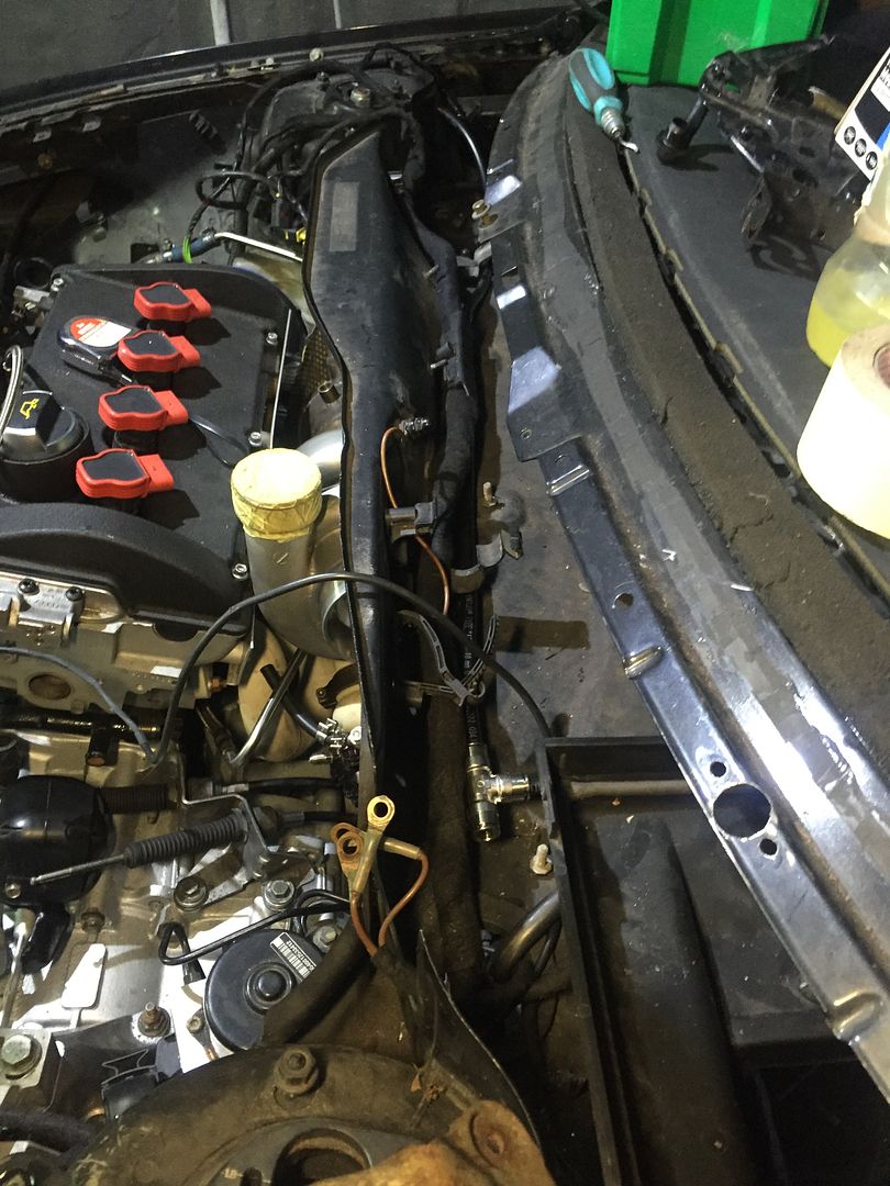
First off after realising how high my inlet manifold sits I thought I best check the clearance to the bonnet.

It's very tight as can only just about get a finger between the two.


I'm going to be cutting part of the inner skin away on the bonnet, especially in the throttle body area to give a little extra clearance. If I still have issues I have a few options including dropping the motor slightly (don't want to do this) or could remove my phenolic gasket spacer. But will wait and see how it goes.

Car looks rather strange with the bonnet on :)


Some hose had arrived over the week to allow me to continue with the fire extinguisher install :)

First off I mounted the other in cabin nozzle, I was going to position it so was central trying to get both passanger and driver, but I changed my mind being a selfish person I directed it all at me and under the dash. In fairness whenever the pins pulled on the system it will most likely be just me in it and I'll be on track.

I used p clips to hold it in place down the side of the tunnel


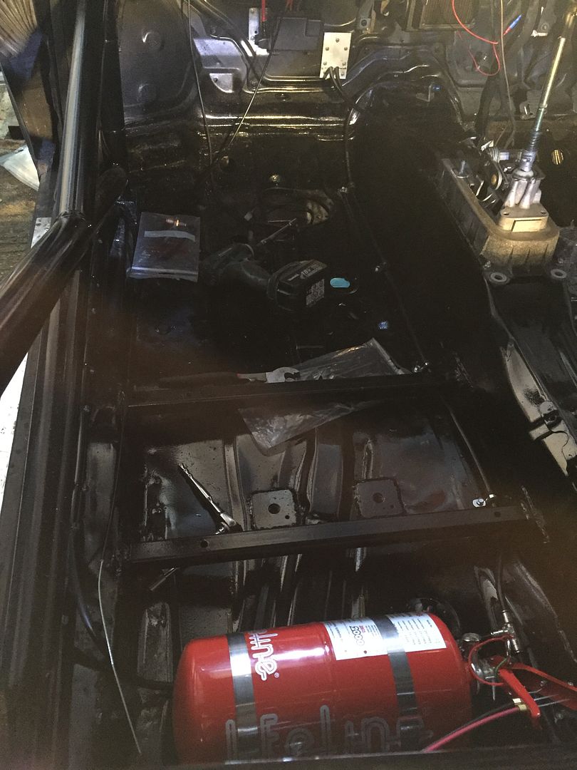
The under bonnet nozzles were next on the menu.

I made some brackets for these and routed the pipework accordingly securing it with p clips and using grommits were possible


This nozzle I pointed a bit off diagonal but I wanted it to be able to reach the brake lines and abs module should something spring a leak over there


I've now pretty much made my mind up on how I want the bay laid out. This meant I could start designing my breather tank ready for AD Fabrication to make up for me :)

I applied the prototype standard of cardboard aided design. I did originally make it far to big, to the point it was going to interfere with the fuel rail inlet pipe and was well over the specified 2L volume required, to reduce the volume I cut a section from the middle out.


I also produced a little sketch to help explain the design in my head.


To mount the tank where I want it I removed the brackets etc that were no longer required.


Only problem is I got a bit carried away with the grinder and removed all other studs etc that are no longer required :D


Then continued on my trigger happy style on the passanger side lol


I was just going to touch up with a bit of black paint to protect the metal but decided that would look diabolical! So I decided to just put a couple of coats of hammerite on to perk it up.


It's not to be a smoothed show car by any means as I've not got it in me to even clean the car myself so will never be going that route! I just like the idea of it being clear and nothing unnecessary present, as and when I want to fix stuff now I'll weld or make my own fixings and just touch back up with hammerite.

When down AD fab they pressed my bushes in for me as I no longer have the luxury of using work equipment and workshops to do so now being a clean environment wearing white lab coats and hair nets in pharmaceutical.


Am hopefully getting a load of bits back soon from AD fab to allow me to start progressing and pushing on a bit more again.

That's all for now
 
What about raising the bonnet a touch at the rear. Seen it done on other BT builds to reduce heat in engine bay. May give you clearance you need and also help with under bonnet heat. (If it works without causing extra drag etc)
 
What about raising the bonnet a touch at the rear. Seen it done on other BT builds to reduce heat in engine bay. May give you clearance you need and also help with under bonnet heat. (If it works without causing extra drag etc)

Yeah that's an option and will give me a little bit but won't give me to much at the front though, another idea I had was to grind away a good part of that corner of the TB and put a shorter bolt in it.

On another note got some bits back from AD fabrications :)


Converted the rad to AN fittings


Alloy piping and silicon to make up the boost pipework.

 
  • Like
Reactions: Essflee, MIGGZ and limbo118118
After AD Fab had welded together my mass of bits it meant was time to fit to the car and start working out hoe this lot was all going to fit.

First off i started sorting out the wastegate lines. These are in 4AN size and should help provide a continuous loop for the coolant when the stat and heater matrix valve are shut.


I was quite lucky that one of the old bulkhead lines fitted straight on but i had to remake the other as was to short to allow for engine movement.

When i went to fit the front cross member and fans i found that the oil filter was very close/touching the conduit for one of the rad fans. As i'm running the OEM oil cooler/heater and a thermostatic sandwich alongside a large oil filter it brings it to close to the rad. To give some extra clearance i ground a recess in the fan support for the conduit to sit in


This then lead me onto the main rad lines which were done in 16AN

As you can see in the first pic the filter sits very close to the cross member


I could of completed the coolant lines and most of the fuel lines but some of the AN 90 degree -6 fittings i ordered were sub standard quality, this was due to the threads being incorrectly cut rendering them useless without the correct tap.

With that in mind i started to work out my boost pipework routing.

The silicon 90 reducer coming straight off of the turbo fouled on the strut brace and wasn't happy with its position so a little tickle with the grinder and file on the comp cover just gave me a little extra to clock the comp cover round a little further


Boost pipework will run a little something like this


Hoping to crack on with the pipework soon and should be shipping my new intercooler over from the other side of the pond shortly.
 
  • Like
Reactions: Scullies, superkarl, Essflee and 1 other person
As miggz said, loving this one and its looking awesome.

Just a thought on your coolant reservoir. Do you have a support bracket for the tank? I cant help but think with engine vibrations and no lift shifting, its going to cause some cracking issues with the welding.
 
  • Like
Reactions: badger5 and StaceyS3
I am really loving this build so much

As miggz said, loving this one and its looking awesome.

Just a thought on your coolant reservoir. Do you have a support bracket for the tank? I cant help but think with engine vibrations and no lift shifting, its going to cause some cracking issues with the welding.

Thanks guys, do like to be different! :)

I have considered about a support or mounting bracket for the reservoir but tbh i never thought it would be as sturdy as it is, it really shocked me tbh as was expecting it to be a lot more flimsy when welded up. I will have another look to see if there's anywhere near to make a support next time i'm out there as better safe then sorry.

On another note its scary to think that when i first bought the car 6-7 years ago that although I was a qualified mechanical engineer who'd happily rebuild anything i come across at work, I'd never changed the oil, plugs or filters on a car and was scared to with little confidence and knowledge i had.

I picked up most of my knowledge from forums etc and now have built confidence to just go ahead and do things that are in my head, i already wish i'd gone more custom on my cage and I think i'll make my own exhaust mani now if this one holds me back.

Theres a few things that will be updating with soon once i'm a bit more developed with them ;)

One of which this old AGN lump i picked up last week will be used to mock stuff up on and also donated its cam cover to be butchered


Also can anyone guess what this lump of rusty stuff off of a french car is???


  • Like
Reactions: SamHendry
Whilst I thoroughly dislike being negative, I must admit that I was a bit concerned when I saw the coolant expansion tank also.

Regardless of how sturdy it feels, it’s a fairly large counterweight (~2kg?) mounted out on a 150mm stick, with all the force going through that single pipe where it attaches to the thin flange. I think given the weight, the lever arm, and the fact that it’s ally there could be problems ahead.

Hopefully I’m wrong, and I’ll be more than happy if I am, but I think it’s worth giving the opinion, even if it just leads to a thought process which decides it’s a non issue and I’m a plonker :laugh
 
Dubster is actually on the money, think i made it to easy lol

I will get a plate welded to the tank to bridge across to the head lifting point to be sure.
There's a few on vortex running a simular setup with the reservoir hanging off of the head flange with no supports or issues but its worth doing so now as you guys suggest to be sure.
 
  • Like
Reactions: Scullies
You gave it away when you said it was off a French car or I would never have guessed

Still not a bad guess though to have got it.

I would usually avoid putting anything french anywhere near my car but this was the best option that didn't cost the earth for what i wanted.
 
My A2 has an electric power steering pump as does the 9N Polos etc..

<tuffty/>

Yeah true but over complicates it as german stuff is a lot more refined than the french :rock: The newer french stuff and german at that require CAN and many other inputs to function.

They use road speed, steering angle position, steering angle torque sensors etc all to determine pump run speeds, which although is clever and reduces the load or even shuts the pump off when not needed, its far to overly complex for what i want and not worth the effort to try and get it to run or integrate on my car.

I will have this pump on a relay to come on with ignition or engine with a overide cut off in line to turn off whne not needed.

It when parking should draw up to 45A and when driving should hover around the low teens/15A.

There was one or two other dumb pumps out there but i liked this shape and design with the built in reservior.

Should be able to get some more pics in the near future up as is painted and tarted up a bit now ;)
 
Got some time on the car here and there over the last couple of days :)

I made a start on the cam cover which was donated by the AGN lump I picked up

Started off by giving it a quick clean with a wire wheel and brake cleaner


Cut off the filler to be relocated in the middle and a lot lower to the cover.


This is roughly what will be like when finished


Put a couple of plates internally to stop oil on exhaust side flicking up the breathers


All taped in place to go to AD Fab for welding :)


Next up went onto the power steering pump. After a clean up with the wire wheel and a touch of paint it looked a lot better.


I bought some exhaust clamps and used some old silicon hose to pad out and hopefully reduce noise


Made a very crude bracket to hold it with the exhaust clamps.


All mounted in the back of the car. Fits in the space quite nicely.


Had an old friend pop round from wickham engineering to do the high pressure line to the rack but he had run out of ferrules on his van so will drop that back over the next few days. If you need any lines etc made up give wickham engineering a shout as helpful guys and can do 99% of stuff


Power steering is now waiting on the hose from wickham and the modified low pressure hardline to come back from ad fab to continue.

Next up I went onto mounting the oil cooler. Annoyingly most of the oil coolers I could find are all just over 300mm long which made mounting a tad more difficult. To give extra room and to allow for my boost pipework I cut the chassis back a touch.


AN10 lines used to connect it to the sandwich plate.


I will be making a mount up for the bottom once I know how the inner arch and bumper sit.

Pretty similar set up for the passanger side for the power steering rad.

I've decided to put a rad on the power steering system as it usually has the cooling loop that runs round to the pump and back as well as the zig zag arrangement in front of the gear box. It's also known for people to have boiled fluid in extreme situations.


The oil cooler will be linked to the modified low pressure hard line and then to return back to the pump at the rear.

As advised I've now made up a bracket to support the header tank.


  • Like
Reactions: Scullies
just read all 64 pages lol and Im not sure if you're any further on since about page 20 :)

top work though, really interesting!
 
  • Like
Reactions: StaceyS3
just read all 64 pages lol and Im not sure if you're any further on since about page 20 :)

top work though, really interesting!

Haha your not wrong, i think it was actually running back then as well so technically a step backwards lol

Thanks though glad you've enjoyed the read, will try and keep it coming
 
  • Like
Reactions: pablo