Prawn and BigAls A3 Track Car
- Thread starter Prawn
- Start date
You are using an out of date browser. It may not display this or other websites correctly.
You should upgrade or use an alternative browser.
You should upgrade or use an alternative browser.

- Joined
- Dec 8, 2006
- Messages
- 12,100
- Reaction score
- 4,340
- Points
- 113
- Location
- Eastleigh
- Website
- twitter.com
Prawn does your breather from catch can tee into the recirc pipe? Neat way to do it if so
Start of a custom catch tank?
Lee is on form tonight
 correct on both counts mate
 ")
I've run an abysmal eBay catch can for years, and always known it's terrible.
I started off by offering some random cardboard boxes up in the engine bay to get a feel for what I wanted:

From there, I spoke to Zak Coles who does lots of these things. He drew up a little sketch, which was pretty good, but me being awkward wanted to change it to open it up to flow better. I saught advice from PT on this also, and we both agreed on ways to make the initial design even better.
Zac was 100% happy to adapt it and work with my ideas, and after a quick chat I drew this last night:

Last edited:
- Joined
- Dec 8, 2006
- Messages
- 12,100
- Reaction score
- 4,340
- Points
- 113
- Location
- Eastleigh
- Website
- twitter.com
Having sent Zak that sketch last night, I expected to go and enjoy my weekend, and probably to hear from him at some point next week about how the catch can was coming on.
When he sent me this pic at 6pm, I thought "that's good, he's started it already"

I was a bit shocked when just a few minutes later he sent me these:
Component parts:

These are the two internal baffles. The openings in each have been calculated to be just over double the CSA of the total inlets / outlets to each chamber:

The basic internal shape before the sides go on:

A few layers of mesh were added in the outlet chamber, to further diffuse any oil vapour that's made it that far

I wanted more than the usual single inlet, with 19mm feeds coming from the crank case and the cam cover, I asked for 2x 19mm inlets:

It seemed daft to vent 2x 19mm inlets through a single 19mm outlet, so the outlet size was bumped up to 25mm to really help it breath freely:

At this point, the top went on:

Pretty incredible welding on this!

Zak asked me if I wanted a drain, or a sump return on the can, at some point I may consider a sump return, but for now I just wanted a drain, so Zak added a threads stub that I can use for a drain in future, and onto that he fitted a neat little drain tap:


All that was left was 2 brackets to allow me to mount it via Riv nuts to the inner wing, and it was finished!


I've not seen it in the metal yet, as these are pics Zak sent me this evening when he made it, but from the pics it looks very good indeed, and sxacty what I had in mind.
More pics to follow and installation once it's in my hands next week

- Joined
- Dec 8, 2006
- Messages
- 12,100
- Reaction score
- 4,340
- Points
- 113
- Location
- Eastleigh
- Website
- twitter.com
I know what you mean Luke, it's pretty and itd be nice to keep it that way, but we all know ally doesn't stay that nice for long.
It'll be getting powdercoated black when it arrives.
I've currently got an old cam cover in the dish washer (don't tell Tori, I'm hoping it's finished before she wakes up!) that I'm going clean that up and have it done orange too.
Then just the inlet manifold and TIP to do and I think the bay will look pretty smart!
Want to get it all in perfect condition under there before the next major change, which I'm sure you can guess at it's been a long time coming
Plan is to do the September Sprint at Curby in 3 weeks with the car as it is, then big changes planned before ADI
It'll be getting powdercoated black when it arrives.
I've currently got an old cam cover in the dish washer (don't tell Tori, I'm hoping it's finished before she wakes up!) that I'm going clean that up and have it done orange too.
Then just the inlet manifold and TIP to do and I think the bay will look pretty smart!
Want to get it all in perfect condition under there before the next major change, which I'm sure you can guess at
it's been a long time coming Plan is to do the September Sprint at Curby in 3 weeks with the car as it is, then big changes planned before ADI
g60leigh
Registered User


Fair play! That's some fine engineering! And there's me struggling to make a ******* airbox! Now I just feel stupid. Good work mate. I enjoy reading these build threads, a real inspiration to all of us.
- Joined
- Dec 8, 2006
- Messages
- 12,100
- Reaction score
- 4,340
- Points
- 113
- Location
- Eastleigh
- Website
- twitter.com
Thanks guys
Car update:
My seriously over priced switch arrived, and whilst I can't wire it in yet due to some vital mission parts, I could at least fit the mount and switch and sit in the car making brum brum noises:
I popped out the original bolts:

Slid the plate in behind the wheel, and dropped in the new 2mm longer bolts.
Simples!

The button falls in perfect reach of my thumb when driving:

Just needs wiring up.
With my steering wheel being removable, the wiring connection obviously also had to be quick release.
For this I bought 2 things. First a 3.5mm stereo jack and a coiled cable, and secondly an XLR mini lockable plug.
I going to try the 3.5mm jack setup first, and I'd that doesn't work, switch to the XLR mini plugs.
Something like this:

Checked lock to lock and no. I sing or snagging or flapping at all

Happy with that idea. Looking forward to seeing how it works.
Next up, I've had one or two stripped cool pack threads on my cam cover for ages, so it was time to replace that. I've had my old one sitting around for ages, so I've cleaned it up to have it powdercoated Orange
It started off really crappy, so I have it a quick hose down in the garden, then decided I was feeling brave and threw it in the dish washer whilst Victoria was still asleep!

After that, I got the nitromors out and attacked it:

With a bit more effort and a wire brush it came out pretty well:

Garage update to come after dinner
- Joined
- Dec 8, 2006
- Messages
- 12,100
- Reaction score
- 4,340
- Points
- 113
- Location
- Eastleigh
- Website
- twitter.com
Garage update
Last week we left off here:

This morning Dan and Ryan arrived bright and early, and made a start:
Corners up first:


Then the long runs and piers between:


A few more courses went on and it was really looking different!


We decided that the original plan of not having a peer in the back wall wasn't going to work. With the narrow towers each side of the window there just wouldn't be any strength, posing not only a stability risk, but possibly a security risk also.
We decided the best course of action was to add peers at this stage, before it was too late to tie them in St all.
Dan Builth second peer up inside the door opening, then used a block on edge to tie it all into the main wall:

By the end of the day the whole lot was 6 courses up, and the window appatures started. All in all I am very happy with how it's looking


It feels enormous at the moment!

The new peers:


It's also looking pretty tidy in the neighbours side too. Hopefully it won't impact them too much once it's sealed and painted

Very excited about spending many productive hours out here after years of dreaming about a garage like this

- Joined
- Mar 28, 2010
- Messages
- 10,073
- Reaction score
- 2,697
- Points
- 113
- Location
- Liverpool/Southport. N west
- Joined
- May 28, 2004
- Messages
- 10,217
- Reaction score
- 2,385
- Points
- 113
- Location
- nr Glos
- Website
- www.badger5.co.uk
Having sent Zak that sketch last night, I expected to go and enjoy my weekend, and probably to hear from him at some point next week about how the catch can was coming on...
I work with Zak and having seen his work up close and the work he's done on another lad at work's 500bhp Astra, I can definitely say I'll be pestering him for stuff for mine. Looking good Nick

jayjay101
Registered User
trust me mate it might feel big now but your soon fill it up! mine felt huge but once you start putting benchs in and stuff soon fills up!mines been a nightmare welding the cage in!!lol

g60leigh
Registered User
Can I throw a question at you Nick? (I know technically that was one) what selection of tyre sizes do you run and what do you feel is best for fit and footprint?
- Joined
- Dec 8, 2006
- Messages
- 12,100
- Reaction score
- 4,340
- Points
- 113
- Location
- Eastleigh
- Website
- twitter.com
Hello mate, all questions welcome as always
Our general road going tyres are a 235/45/17 khumo ku36. We went 235/45 to gain a little extra height mainly for splitter clearance on the road. They're pretty good on track, but don't offer the same sharp turn in as a slightly smaller 225/45. Tb Boa probably partly due to the taller size, and partly down to a softer sidewall being a road based tyre. Ride comfort is also best in these.
Road legal semis we use for the sprints are 225/45/17 yoko A048's, these are brilliant and with a stiff sidewall give great turn in, but I do find the splitter hitting the ground a LOT more often, despite the height difference only being 8-9mm. Ride comfort notably worse.
Slicks on track are a 235-610-17, similar width, but a much lower profile again. This lowers the car another 12mm and makes it very much track only in height terms (not that slicks are road legal anyway)
Last up the wets we have are 245-620-17. Slightly taller than the slicks, and wider with a huge open tread pattern. The car doesn't feel as solid on these, but wet conditions they're fantastic.
- Joined
- Dec 8, 2006
- Messages
- 12,100
- Reaction score
- 4,340
- Points
- 113
- Location
- Eastleigh
- Website
- twitter.com
Catch can arrived.
No pics, but it's beautiful. And it'll fit well in the bay. Off for powdercoating this week hopefully.
No pics, but it's beautiful. And it'll fit well in the bay. Off for powdercoating this week hopefully.

Nick_sheep
All The Gears But No Ideas
- Joined
- Dec 8, 2006
- Messages
- 12,100
- Reaction score
- 4,340
- Points
- 113
- Location
- Eastleigh
- Website
- twitter.com
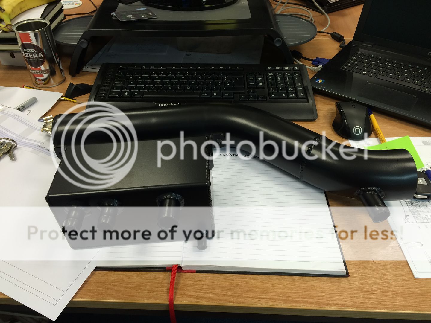
I cleaned up my TIP on Sunday, ready for a trip to the powdercoaters:


That, along with the stripped cam cover and the shiney new catch can have now gone to be coated.
The TIP and catch can are going black, and the cam cover will be done bright orange I'm quite looking foward to smartening up the engine bay a bit! I just need to whip off the inlet manifold and give it a fresh coat of satin black and it'll really tidy things up.
We went for a drive on Suinday morning for another little breakfast meet at Loomies, my new boss Tony is very into his cars, and came along with Andy and I in his immaculate 205 gti, it was a very fun convoy!


In a rare change to the usual, I followed the guys on the way back instead of leading. It was nice to save some fuel for a change
Good times


That, along with the stripped cam cover and the shiney new catch can have now gone to be coated.
The TIP and catch can are going black, and the cam cover will be done bright orange
I'm quite looking foward to smartening up the engine bay a bit! I just need to whip off the inlet manifold and give it a fresh coat of satin black and it'll really tidy things up.We went for a drive on Suinday morning for another little breakfast meet at Loomies, my new boss Tony is very into his cars, and came along with Andy and I in his immaculate 205 gti, it was a very fun convoy!


In a rare change to the usual, I followed the guys on the way back instead of leading. It was nice to save some fuel for a change
Good times
- Joined
- May 28, 2004
- Messages
- 10,217
- Reaction score
- 2,385
- Points
- 113
- Location
- nr Glos
- Website
- www.badger5.co.uk
just finished mapping an emerald K6 plug and play converted A3 AGU earlier.
chop chop
chop chop
- Joined
- Dec 8, 2006
- Messages
- 12,100
- Reaction score
- 4,340
- Points
- 113
- Location
- Eastleigh
- Website
- twitter.com
I'm on the case Mr. B, fear not!
I collected my freshly powdercoated bits yesterday. Very happy with how they've come out. Glad I went black on the TIP and catch can as the Orange is BRIGHT

It's certainly going to brighten up the bay!

I also had this door sill made for the rear access door of the garage, chequer plate to hint to what lies within

fear not!I collected my freshly powdercoated bits yesterday. Very happy with how they've come out. Glad I went black on the TIP and catch can as the Orange is BRIGHT


It's certainly going to brighten up the bay!

I also had this door sill made for the rear access door of the garage, chequer plate to hint to what lies within

- Joined
- Dec 8, 2006
- Messages
- 12,100
- Reaction score
- 4,340
- Points
- 113
- Location
- Eastleigh
- Website
- twitter.com
Exciting step yesterday, the blockwork is up to finished height!
The first block of the last course goes on!

Dan got a second bricky in for the day to ensure he got it finished. They made short work of it, and before lunchtime both sides were up to full height:


The door frame was measured and the lintels set in place. Then we tested the door in the frame (it's backwards in this pic)

The lintels and final blocks across the back wall were finished off:


Once the lads had cleaned up and left, it was time to park something in there and see how it feels.
With the track car being elsewhere currently, all I had was the van:

Both doors fully open, still with plenty of room each side and room for the shelves down the passenger side too:

Masses of room down each side:

And loads of room behind with the van pushed right forward:

Very very happy with how it's coming along.
Next up, a roof!

- Joined
- Dec 8, 2006
- Messages
- 12,100
- Reaction score
- 4,340
- Points
- 113
- Location
- Eastleigh
- Website
- twitter.com
Soon my friend, soon
The sun came out today, so I dug the car out of the unit and gave it a wipe over.
It comes up ok for 17 years old and 230k miles!

As it was out, it seemed a shame not to take it for a brief spin:

The sun came out today, so I dug the car out of the unit and gave it a wipe over.
It comes up ok for 17 years old and 230k miles!

As it was out, it seemed a shame not to take it for a brief spin:

- Joined
- Dec 8, 2006
- Messages
- 12,100
- Reaction score
- 4,340
- Points
- 113
- Location
- Eastleigh
- Website
- twitter.com
Garage roof related question are you doing it or getting someone in??
Must be diy'able??
Allow me to introduce myself

I should be ok on the roofing side of things
Nick is that a hands free kit in the RaceCar? ha ha
And what is 14.9?
Not just any hands free kit my man, it's a genuine antique parrot ck3200 colour! Haha. All of which will be going this winter.
14.9 is AFR on idle. Little display above is EGT