AH Fab / Ebay / Forge S3/A3 FMIC installs (image heavy)

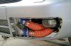
How much is this intercollers ? It really looks amazing!!!

Be more specific.. this thread is full of them... use the quote functionality of the forum... most of these intercooler cores can be found on eBay.. pointless posting links as its too fluid and links expire as soon as they go up...

Up to date pricing info can be found by using the info provided on this thread and looking on eBay for the products...

<tuffty/>
 
After a bit of clarification if someone up for helping?

I have a Ver1 AH fabs fitted and going to upgrade the pipework ready for mapping.

As I understand it I need:
2x 63mm ID silicone 90's
2x 63mm OD alloy 90's
2x 63mm OD alloy 90's welding to my intercooler.

Is that everything I need?
Also do I need a certain thickness alloy for the 90's welding to the intercooler or longer length.

Thanks.

I used off the shelf bends from Forge on mine... your list is fine apart from you might need a silicon joiner to go from the MAP tube to the passenger side alloy bend as the OE rubber one may not flex enough to go over the 63mm end...

I am assuming by 'thickness' you mean length of leg on the bends?... tbh I don't recall the actual length as it was pretty much place them on the modded FMIC and bring them in as tight as poss to allow clearance of the fogs... you may still find you have to trim a little off the fog brackets and the maybe the bumper too...

<tuffty/>
 
Thanks Tuffty. By thickness I'm meaning gauge of metal. So its thick enough to weld without blowing through.
I will order up another piece of silicone to go over the map pipe then. Rather have some to hand than fight with it. Will a straight 63mm piece do for that or would a reducer be needed.

Cheers for the assist

The bends are just a std thickness... the AH Fabs end tanks should be the same gauge as they are made from sheet rather than cast alloy..

Straight 63 should be ok... been a while since I last did one so can't remember what I used... only thing to consider is that the MAP tube is 60mm... 63mm will clamp down but use decent JCS clips... if concerned then a 60mm should squeeze over the 63mm alloy with a little fairy liquid and a bit of swearing :)

<tuffty/>
 
  • Like
Reactions: g60leigh
Hi guys!

My new FMIC kit just arrived from UK today, i bought it from universal intercoolers so i could keep my fog lighter. BUT I got one question, what do I do with the sensors thats attached on the piper that goes to the old SMIC? I can see that on all the pictures around They are just dangeling down, do i need them, or can i just route the new intercooler straight up without them

Alex

I'm assuming you have an A3 with an AUM engine code based on what you have said... the sensor in question is the MAP sensor and its important its fitted into the pipework correctly... some FMIC 'kits' come with a MAP sensor tube (although all the ones I have seen leak)... if you are making your own pipes then get a MAP sensor tube from Forge Motorsport

<tuffty/>
Oh sorry, I forlot to say that its an Audi S3 2001 AMK Engine. I'll guess i have to buy that MAP sensor tube anyway or can I maybe reroute the new piping to go through the old pipe thats got the fitting for the sensor? :)
Sorry about the norweglish writing..


Edit:
Just ha da better look inside the Engine bay no, and it Looks like the new FMIC is gonna be routed info the old inlet thats just before the old SMIC, is that correct? Couse' the SMIC hasn't got any sensor on it self..
 
Last edited:
Oh sorry, I forlot to say that its an Audi S3 2001 AMK Engine. I'll guess i have to buy that MAP sensor tube anyway or can I maybe reroute the new piping to go through the old pipe thats got the fitting for the sensor? :)
Sorry about the norweglish writing..


Edit:
Just ha da better look inside the Engine bay no, and it Looks like the new FMIC is gonna be routed info the old inlet thats just before the old SMIC, is that correct? Couse' the SMIC hasn't got any sensor on it self..


Ok... that makes things a lot easier... S3's have a MAP sensor tube that runs between the battery and the headlight... there are plenty of posts in this thread showing you what you need and how to fit various FMIC's on S3's...

There are two SMIC's on an S3 by the way :)

<tuffty/>
 
Ok... that makes things a lot easier... S3's have a MAP sensor tube that runs between the battery and the headlight... there are plenty of posts in this thread showing you what you need and how to fit various FMIC's on S3's...

There are two SMIC's on an S3 by the way :)

<tuffty/>
Thanks <tuffty/> I'll read some more here then and see if i can Get some tips :) Should be plug and play actually apart from cutting in the cash bar.. Really Looking forward to see the result :D

Yes, i know theres two, Hehe :p
 
At what temperature does the ECU start pulling back the power? I take it ******* the ignition?
 
Rather than post pics I will just give a link to my thread where I have installed my FMIC http://www.audi-sport.net/vb/a3-s3-forum-8l-chassis/168515-fmic-fitted.html

It starts with me using a small FMIC which did not work well when I went to get my car custom mapped for stage 2. So on Page 3 you will see I have changed the cooler for a Welly Cooler with 63mm ends welded on which I have managed to fit and keep my OEm fog lights and grills.
 
hello fast people
i now mounting my 600x300x76 fmic
after the ic iam wondering fit 3" piping, can i achive some gains our no worth the extra money?
the turbo is an hybrid
 
hello fast people
i now mounting my 600x300x76 fmic
after the ic iam wondering fit 3" piping, can i achive some gains our no worth the extra money?
the turbo is an hybrid

Laggy is the word really... the turbo will spend more time trying to build pressure in larger pipework... for 63mm is big enough for almost any turbo on a 1.8t... I use 63mm on my GT3582r...

<tuffty/>
 
63mm inside our outside

OD for alloy pipework... its a standard size... silicone is 63mm ID as this is designed to fit over 63mm OD alloy pipework... S3 hard pipes are 60mm OD for reference...

<tuffty/>
 
  • Like
Reactions: Miguel_S#
does where the map sensor on a ARY engined car is put in a fmic system make much difference? im welding my boss in a alloy bend which would practically be in the same position that the old SMIC would have been. pretty sure it that would be ideal but always worth asking!
 
IMG 0936IMG 0938IMG 0945IMG 0945IMG 0947IMG 0946IMG 0948IMG 0950

I am going to black mesh the whole front grill tomorrow, and since the fogs are gone but the wiring is there, LED drls are going to go on, she'll look very unique. All the pipe work is silfab 2 guys, simply clamped directly to each section, 2 ply, copper wire reinforced tubing rated to about a few hundred degrees C and about 150psi (the clamps will give way before the pipe work does!) Will keep everyone in the loop on how this all holds up!
 
View attachment 37460View attachment 37461View attachment 37462View attachment 37462View attachment 37463View attachment 37464View attachment 37465View attachment 37466

I am going to black mesh the whole front grill tomorrow, and since the fogs are gone but the wiring is there, LED drls are going to go on, she'll look very unique. All the pipe work is silfab 2 guys, simply clamped directly to each section, 2 ply, copper wire reinforced tubing rated to about a few hundred degrees C and about 150psi (the clamps will give way before the pipe work does!) Will keep everyone in the loop on how this all holds up!

That hose you are using looks like its will leak like a sieve

<tuffty/>
 
she's holding boost 100% at the moment, time will tell! There are what look like loose ends in some of the pics but I can assure you they're on extremely tight, we had to remove some of the copper wire from the end of each pipe to make sure it was elastic enough to juuust fit over the cooler and general connections, tb, charge pipe etc, but where the clamp ends the loose silicone looks very sloppy and frayed, but it is purely a cosmetic thing.

She was taken for a very heavy spin under full boost, we had one clamp come loose due to the bumper pushing on it and the clamp being very old, put on a new clamp and so far so good.

Very simple install after the difficulties of getting everything off, also fashioned a very interesting way to attaching the intercooler. We put brackets beneath the cooler which slid into a little groove between the chassis and radiator, fit like a glove, brackets went back about 3 inches, this alone held the intercooler with it resting against the crash bar. We then had a bracket welded on the top of the cooler (central) with a hole in it (this came with the cooler as it was a $70 second hand ebay grab). Cut the horn bracket to where you can see in the picture, drilled a hole (not in the pictures) which lined up with the hole on the bracket of the intercooler, 2 stainless steel cable ties fastened it beyond tight. Its sitting flush in the crash bar, is held by the two arms below that were simply slid into place, and cable tied on top (resting behind the horn bar, which you can see, just hadn't cable tied it yet) No welding of any kind required. Does not budge a mm.

I have been very interested in this silfab for intercoolers for a while as a fellow was running some on his twin turbo b5, he had no issues except for some melting problems as his was running extremely close to his manifold (I think he replaced his charge pipe with silfab) If this holds up, it cost me $100 for 2 meters of pipe, used all the old clamps (bar 1) $70 for the intercooler, $5 for stainless steel cable ties. All in for around $200 and a days work.

If I have problems I will stainless steel and silicone join the setup but so far so good.
 
Last edited:
So she's all finished, had to cut back the front bottom grill to make it fit, some auto mesh glued on, sprayed black and everything is nice and secure. Silfab 2 is still holding strong, quite a sound change across the turbo, intake and dv with the new cooler. Here's one quick before pic of the empty front lower grill followed by the mod. View attachment 37673IMG 0985IMG 0987IMG 0991IMG 0992S3 25S3 26S3 27
 

Attachments

  • IMG_0994.jpg
    IMG_0994.jpg
    94.8 KB · Views: 655
  • IMG_0995.jpg
    IMG_0995.jpg
    92.7 KB · Views: 644
Last edited:
curious and incorrect choice of flex hose for holding boost pressures me thinks

wonder how long before it splits on you.
 
Im sort of playing this as a test subject for the stuff. Its rated to a proven 45psi and 600degrees so I'm feeling good so far! Had a couple of clamp slips, (and the tip tried to blow itself loose off the intake....?) since putting it all together. If it holds for a year (and after my custom map in 2 months) i'll start recommending it to everyone; if not, i'll post pics of the carnage.

basic shpeel:

Construction:
Smooth inner ply and cover ply of silicone-coated, woven fiberglass. Superior air flow and minimum friction losses. Chemically treated, helically wound, spring steel wire for flexibility. Double, continuous filament, silicone-coated treated fiberglass cord. Vulcanized for long service life. Lightweight, non-kinking.
 
We use that hose on the machines at work for a drain on hydraulic bar feeders. Even then they don't seal very well due to the spiral of copper. It's the kind of hose that will take 45psi if you can seal it to that but will balloon to about 4 times the size. Good luck with your trial tho.
 
Well we obviously didn't and wouldn't try and seal the clamps of a pressurised turbo system over a copper wire? :p we threaded the wire out of roughly 2-3inches off the end of each attached segment to allow for a firm air tight seal beneath every clamp. IMG 0984 (beneath the clamp and to the left has been threaded i.e. no wire) to the right you can see the wire is left to retain full support of the pipe. (You can ask for certain lengths to come with straight un wired cuffs) The pipework does shudder and visually expands several mm under heavy boost but so far it is holding full boost which we would understand to mean it is holding a complete seal.
 
...but so far it is holding full boost which we would understand to mean it is holding a complete seal.

...not really no... the ECU is clever enough to up duty cycle on the N75 if it sees less boost on the MAP sensor than its requesting.. small leaks will essentially be compensated for by this and by the fuel trims...

Obviously its your car and your choice but I have to agree with all the comments so far... this hose is the wrong choice for this application... I can understand trying alternatives if they are fit for purpose but this stuff simply isn't suited for a turbo charged application... even the steel reinforced flexi hose that the like of Forge supply has more layers and is more like the normal silicon hose than this stuff...

<tuffty/>
 
ok ok what i'll do is go get a smoke test done next week, i'll film it and take some happy snaps to satiate my curiosity and post them up here. Though I just cannot see for the life of me how this is leaking, anywhere, the silicone has moulded itself so tightly around every join it just does not look possible... there are no tares, everything is completely flat, flush, and ball achingly tight :I Everything in fact looks like it has sealed and is grabbing the joins better than any of the stock pipes did. BUT! I am possibly wrong! I'll post up all the findings of the smoke test.

(all these comments are good, it's giving me signs of what to look for if I start having problems. We are testing this as its so insanely cheap and easy to install, but if we test and prove it fails and is full of negative pitfalls, then I will post the findings and tell people to avoid, otherwise, if we find no problems all I can do is say go for it!)

The only real problem is why would this setup cause the intake and TIP to try and "blow" apart? The turbo seems to be louder and spool much harder, possible leak in the oem setup?
 
Last edited:
If you have taken the copper out it will seal as well as any other hose but still very thin. Hense why it is ballooning. I have no doubts it will work but your lag must be pretty bad due to it having to blow up your pipes to get your pressure. Therefore your turbo is working harder too. If people manage to split conventional hoses then I think these will split maybe within a few weeks maybe a month. Will be interesting to see what happens.
 
The lag is quite considerably less, (I may have overstated that the silfab expands as much as you believe, it is closer to less than a 1mm, if that, it's the network that expands, it visually flexes because the pipes are not tied down, but the actual pipe has not expanded anything beyond a mm -this is the purpose of the helical wire spiral that does not allow the pipe to inflate, for this to occur I believe the 50psi max would have to be held for quite some time and the silicone would possibly tare away from the wire at this point?- I will make a video of this flex effect so you can see clearer)

There are several very very similar looking pipes on the market, same braid, colour but different texture and strength and are made of entirely different substances but look identical in appearance? I think maybe you are thinking of something that visually appears the same but is not? To get through this pipe you need nothing short of a hacksaw (which is what we used) On the horizontal it could not tare from a the mere boost of a k04, even a mapped one. Here is the pipe in black: IMG 3862

I think because I am less laggy on the turbo front and spooling much faster my original leak would have been within the oem cooler network somewhere. perhaps I had a cracked oem cooler -though they look in great shape- so was used to slow spool? I have lost a couple to a few feet of pipe, I have drastically reduced the amount of bends and angles (with absolutely no 90degree turns) I think this may also have helped boost?

I will let everyone know if and when it splits (I'll take photos of the pipes that gave, where and how; eg around a certain area of strained wire, at a coupling, a part that frayed against body work etc)I'm going to watch and test this whole thing rigorously. A pipe network that's complete diy and parts that are drastically cheaper? And I have been warned so am now aware there could be apparent issues,so will expect it to go, and presently surprised and happy if it doesn't

this fellows only issues were a manifold contact heat issue:
 

Attachments

  • image.jpg
    image.jpg
    99 KB · Views: 680
  • image.jpg
    image.jpg
    65.8 KB · Views: 807
  • image.jpg
    image.jpg
    71.7 KB · Views: 623
Last edited:
It is much thicker then the stuff we use. But does it not expand length ways like a spring? It's an interesting concept I'm quite excited to see the results really. Did you have it tested power wise before? So you can compare.
 
This stuff doesn't expand length ways, it would tear before it expanded, it doesn't compress either - like a slinky-, it only bends. From factory the stats are medium pressure applications up to 45psi (after my map 23-24psi? so feel very safe) and heat resistant to 600degrees. That's all I read before I bought it, its fairly cheap at $50 per meter, and I was doing the fmic anyway, definitely felt its worth the experiment.

(I think the main issues I will have from this are rubbing and it eventually being worn through, may be worth wrapping these pipes in something after install) Also it is extremely light, literally not a blip on the scale radar, definitely an added bonus.

I have given her some very very hard runs since the install, (just got back from one) with the goal to find literally, weak links, but still so far so good! And a bonus, my idle has settled to almost perfect for the first time since owning her!

If this works well I think intercool pipe fabers and silicone hose sellers are going to have need to worry! :p

Here is a good pic of how flexible it is, and another pic of the set lengths you can get with cufs:

Silfab 140
 
problem with hose like that is it will always want to straighten when under pressure which will cause it to move around a lot rubbing on manyt things in the process

ok as a bodge to get it going, but long term you can t beat doing it with proper hoses and pipes
 
  • Like
Reactions: Nick_sheep
in reading through the thread most people have been referring to MrSilicone's eBay store to get the silicone hoses that go from the FMIC to join the existing pipework in the S3. I checked through his store and cannot see anything for the S3, so I was wondering if anyone knew of a place to get the 2.5" pipework on its own, that allows you to keep your foglights (I will source the intercooler separately).

Thanks
 
554543 10151208264486326 827185689 n


This intercooler any good for an upgrade, i think its from autobahn88, need to check dimensions. I dont really want to lose the fog lights too.
 
Hey guys. Is it possible for someone to upload some more pics showing an idea of how much to cut on the outside of the fog light grill when fitting the welly cooler.

I followed the Welly Cooler (post 13 of this thread) and don't wanna cut more than I need to..

Anyone's help will be super please!