

Oil Catch Can mini group buy anyone? including PCV system simplification.
- Thread starter OllieH
- Start date
You are using an out of date browser. It may not display this or other websites correctly.
You should upgrade or use an alternative browser.
You should upgrade or use an alternative browser.
sportstractor
Chugger
cool, only downside I can see with that is that your still introduction oil vapours into the inlet system... obviously a vacuum is required. Just a suggestion and it is a bit of a pain, but have you thought of bosing a jet into the exhaust system. Iv seen this done on hondas, the jet attached at the right angle creates a vacuum (venturi effect  ) which would link back to your catch tank. Considered this at all? Saying all this, I probably would just let it go into inlet lol.
This im gonna have to get me a catch tank in the near future then.
) which would link back to your catch tank. Considered this at all? Saying all this, I probably would just let it go into inlet lol.This im gonna have to get me a catch tank in the near future then.
OllieH
Registered User
deleting the pcv system? what is it for?
It allows the vacuum in the inlet manifold when the throttlebody is closed, and the vacuum created in the TIP when accelerating to draw the blow-by gasses out of the crankcase and rocker. It is designed so that the pressure maintained in the crankcase is slightly less than atmospheric. That way, there can be no seepage of oil through the gaskets etc, which would contribute to the cars emissions. The setup we are going to do has been tested many times on the ukmkiv forum, showing having no pcv system has no effect on the engine, and is purely an emissions based fitment that the VAG group have done to meet stringent emission laws. The crank and rocker are still allowed to vent, but now through the catch can, and the pressure is still maintained by retaining the PRV (Pressure Regulating Valve).
cool, only downside I can see with that is that your still introduction oil vapours into the inlet system... obviously a vacuum is required. Just a suggestion and it is a bit of a pain, but have you thought of bosing a jet into the exhaust system. Iv seen this done on hondas, the jet attached at the right angle creates a vacuum (venturi effect
This im gonna have to get me a catch tank in the near future then.
There shouldn't be any oil vapours entering the TIP as this is what the catch can is for. There will still be a vacuum created in the TIP when accelerating which will help draw the gasses through, but is not actually needed as their is enough pressure in the crankcase to push the gasses through. As said above, the PRV will be retained which will also help maintain the crankcase pressure. Many people on ukmkiv forum have actually deleted the PRV aswell, without any problems, but I will be keeping it. Sounds like too much hassle with the exhaust system, especially if this setup works.
The Doctor
Registered User
- Joined
- Jul 25, 2009
- Messages
- 1,390
- Reaction score
- 190
- Points
- 63
- Location
- Notts
- Website
- www.wbmcc.com
Great thread, but I need a big piece of brown paper, some felt tip pens and a full print-out of this thread to get this straight in my head before I start the install. Each bit makes sense, but when I go away & come back 5 minutes later I'm confused again! 
ok chaps, done mine this weekend, heres the link to my fitting guide
to be fair it was a pain in the back side, only tip id give is make sure you cut your pipework before connecting to the T piece or can, as once you fit them you will spend your life removing them if they need to come off....also where the pipe fits the rocker cover, you WILL need some grease to get it on, my hands have chaffing marks where i forced it on....seriously looks and feels like ive been self loving far too much!!
http://www.audi-sport.net/vb/showth...-A3-build-thread-(image-heavy)&highlight=fmic

OllieH
Registered User
Cheers for that.:icon_thumright: I will have a good look through your build thread at some point. My hose connections turned up last week but haven't had the chance to look into it yet as I spent all weekend rebuilding my bathroom after the missis' hamster decided to do a Houdini behind the panels Next chance for me now will be next weekend!!
Next chance for me now will be next weekend!!no worries Ollie..... make sure you get hold of some gloves before you venture beneath the manifold, will save you half a day washing your hands!! ")
Hamster in the bathroom? You sure you werent trying the Richard Gear trickery
Hamster in the bathroom? You sure you werent trying the Richard Gear trickery
- Joined
- Oct 27, 2006
- Messages
- 2,851
- Reaction score
- 110
- Points
- 63
Sorry if this has been asked many times in this thread. ( i get little time on line so only speed read this thread,
Is there NO down side to fitting the can like this?
I am going to be fitting a catch can but was told to fit a "baffled can" in line ( just before the breather pipe enters the TIP)
Is there NO down side to fitting the can like this?
I am going to be fitting a catch can but was told to fit a "baffled can" in line ( just before the breather pipe enters the TIP)
The catch can is baffled internally so that would negate the need for any further 'baffles' before it enters the TIP.
The only downside that I can imagine is if it's not maintained regularly, the can filling up to a point where it stops working and becomes blocked creating back pressure over what the system can handle, posibly causing oil seepage into the bores but that would be in extreme cases of owners becoming too lazy (note to self - check can regularly and drain....). Somebody correct me if I'm wrong...
The only downside that I can imagine is if it's not maintained regularly, the can filling up to a point where it stops working and becomes blocked creating back pressure over what the system can handle, posibly causing oil seepage into the bores but that would be in extreme cases of owners becoming too lazy (note to self - check can regularly and drain....). Somebody correct me if I'm wrong...

good thread fellas.
question for you though. im sorting out some issues on an AGU at the mo. there is a breather hose on the bottom of the inlet manifold going to what looks like a one way valve. the hose is perished and split. any idea on what ID it is as it needs to be replaced.
thanks
question for you though. im sorting out some issues on an AGU at the mo. there is a breather hose on the bottom of the inlet manifold going to what looks like a one way valve. the hose is perished and split. any idea on what ID it is as it needs to be replaced.
thanks
Hi Matt,
According to the UKMKIV's thread linked/posted earlier, the ID is 3/8", see here almost half way down where he uses a bolt to cap the hose under the inlet manifold: http://uk-mkivs.net/forums/t/269734.aspx?PageIndex=1
I reckon the ID will be the same whether it's an AUM / AGU / AUQ personally...
HTH,
OllieH
Registered User
As Imteyaz said, I think most of it is 3/8. There might be some 1/2" in there aswell.
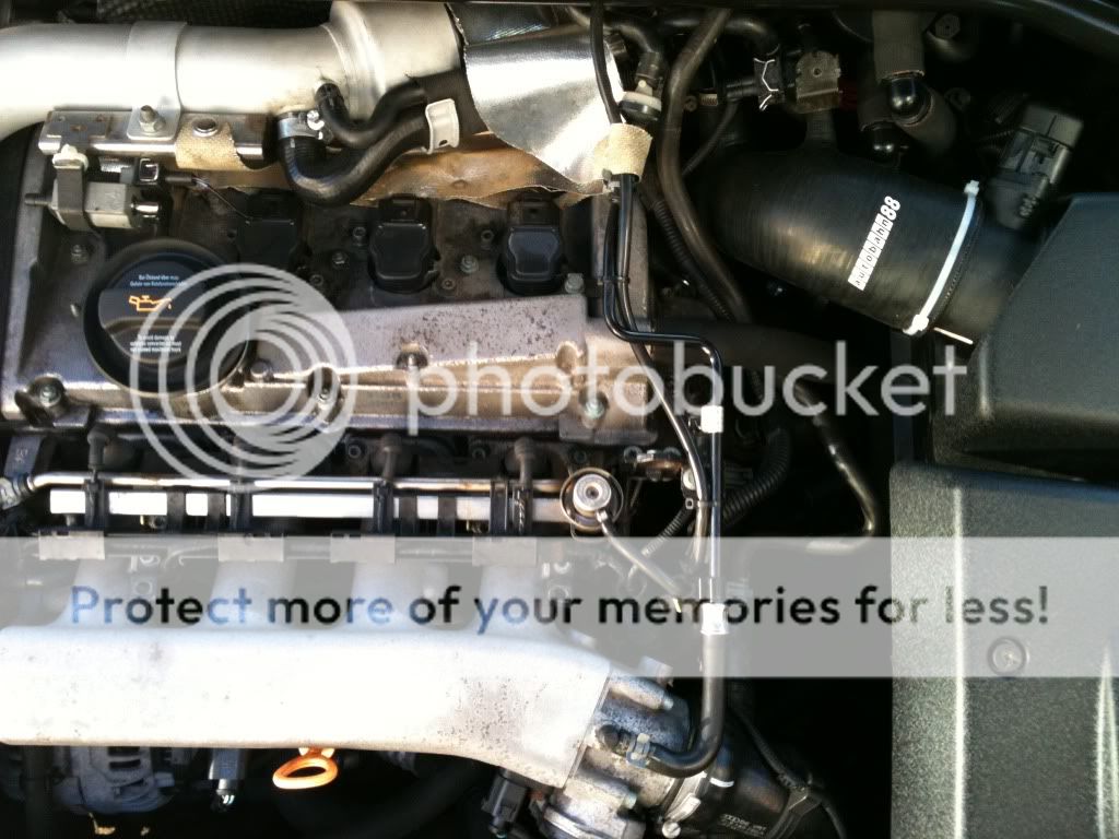
Is the pipe in question any of these?:

Is the pipe in question any of these?:

sportstractor
Chugger
As there is so many of you ripping this lot out, would anybody like to send any of it my way. I need pretty much everything after the T coming from crankcase, mainly the solid plastic pipework, ideally not split. Iv just orders the rubber bit in silicone, decided to go for this route as Id like to keep it as standard as possible. Give me a PM, Thanks.
sportstractor
Chugger
OllieH
Registered User
nobody?
Sorry, mine has a couple of splits in it and is in bits anyway where I've robbed parts for other stuff. Bear in mind people will be re-using the check valve for their brake servo line (the one just to the left of centre on the above pic which hasn't got a part number attached to it.) I had to cut the hard pipes to get this out aswell.
- Joined
- Dec 2, 2008
- Messages
- 17,400
- Reaction score
- 1,104
- Points
- 113
OllieH
Registered User
Ollie, Is your can all rigged up and mounted now?
Yep, finished Monday night. Will be posting a few pics up tonight after work. :thumbsup:
- Joined
- Dec 2, 2008
- Messages
- 17,400
- Reaction score
- 1,104
- Points
- 113
Good man. I still need to get hold of some silicon and jubilee clips to block off the manifold. I'll wait for your pics too :icon_thumright:
- Joined
- Dec 8, 2006
- Messages
- 12,100
- Reaction score
- 4,340
- Points
- 113
- Location
- Eastleigh
- Website
- twitter.com
hayes, don't eb such a ******* ****, as standard as possible? that's not like you at all!
Buy an ebay round catch tank for £30, go to your local pertek who can give you some fittings with 19mm push fit and a 1/2 thread to suit the tank, then all you need is 2m of bilge pipe and a 19mm T, and that's it!
Shouldn't take more than about an hour to do either.....
Buy an ebay round catch tank for £30, go to your local pertek who can give you some fittings with 19mm push fit and a 1/2 thread to suit the tank, then all you need is 2m of bilge pipe and a 19mm T, and that's it!
Shouldn't take more than about an hour to do either.....
sportstractor
Chugger
Sorry, mine has a couple of splits in it and is in bits anyway where I've robbed parts for other stuff. Bear in mind people will be re-using the check valve for their brake servo line (the one just to the left of centre on the above pic which hasn't got a part number attached to it.) I had to cut the hard pipes to get this out aswell.
ah well mine can be fixed i suppose.
with regards to the check valve in the T-peice, when I had mine off it was letting by ever so slightly when i blew down it, not sure if the seal is ment to be 100% under positive pressure.
I could also do with the solid plastic pipe that goes from the T to the hockey puk thing

- Joined
- Oct 27, 2006
- Messages
- 2,851
- Reaction score
- 110
- Points
- 63
Hi,
I read in this thread that the inlet and outlet for the catch tank need to be 19mm to allow the engine to breath freely.
Is this real the case? As im sure the pipe which goes back into the TIP is smaller than that.
I was planning on leaving my Breather system in place but adding a catch tank in line with the hose that goes from the hockey puck to the tip.
The inlet and outlet on the catch tank ive got is 15mm.
you guys think this will work?
OllieH
Registered User
Hi,
I read in this thread that the inlet and outlet for the catch tank need to be 19mm to allow the engine to breath freely.
Is this real the case? As im sure the pipe which goes back into the TIP is smaller than that.
I was planning on leaving my Breather system in place but adding a catch tank in line with the hose that goes from the hockey puck to the tip.
The inlet and outlet on the catch tank ive got is 15mm.
you guys think this will work?
I would think you'll be alright. The ID of the PCV valve on the crank breather is less than 19mm anyway, so there's already a restriction there. We went for the 19mm can connections because of the recommendations on the ukmkiv, and just to be safe.
Dont get me wrong... i would love the can you lads have and to remove things that only cause problems.
You want me pop round over the bank holiday mate and show you my set up, while im there i could lend your vag-com to try and align my head lights
hahasportstractor
Chugger
hayes, don't eb such a ******* ****, as standard as possible? that's not like you at all!
Buy an ebay round catch tank for £30, go to your local pertek who can give you some fittings with 19mm push fit and a 1/2 thread to suit the tank, then all you need is 2m of bilge pipe and a 19mm T, and that's it!
Shouldn't take more than about an hour to do either.....
nah cant be *****, just looks **** with rubber hose running across the engine bay and looks even worse when i eventually sell it. the standard system works well if properly maintained, iv replaced the weaks points with silicone parts and going to replace check valves, simples. This catch tank business is a bit overkill for such a standard car, no point changing for sake of it.
OllieH
Registered User
Right then, managed to get the rest of my catch can install finished, so here's what I did.
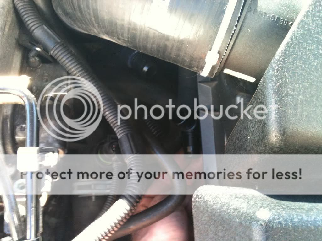
Decided that I didn't want to mount it with the bracket anymore as previously shown:

And decided to have another go at getting my hand into the pollen filter flap so I could mount straight onto the firewall. Had to remove the TIP so I could drill a hole through the bulkhead. I positioned the hole about 10mm to the right and 10mm down from the right hand stud (which I had previously cut off) There are cable runs behind the firewall which come very close to where you will be drilling. All I did was hold the cables up while I drilled through. Be very carefull when doing this. Don't forget you can still mount using the bracket and left hand stud as shown on page 5 of this thread. You'll wanna use a round file to get rid of the burrs aswell afterwards.
Next was to remove this lot:

Most of you will need to remove this lot aswell, which I had already done. ( I've already written a guide for this part which includes blanking the relevant connections and fitting the brake servo feed pipe with check valve. I think it's on page 4 of this thread):
Then remove the crank breather 90 degree pipe (make sure you don't lose the green o-ring) and the PRV valve as you'll need to reuse them.


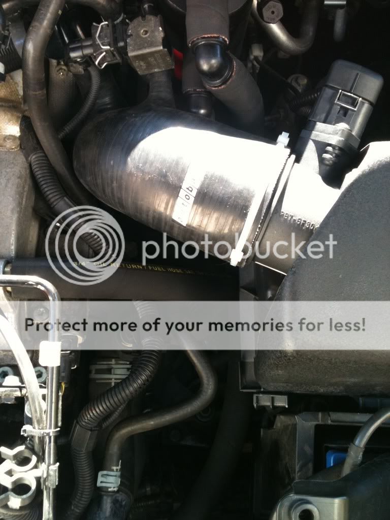
Next, attach the PRV directly to the TIP connection, in the same inlet/outlet configuration as before, just without the extention pipe. Point the inlet up towards the catch can:
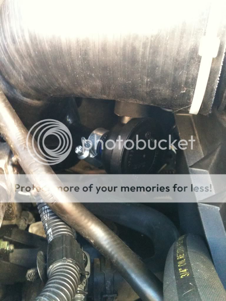
This is what it looks like from the top:
You can see that all I've done is use a 90 degree 19mm pipe connection to direct the can outlet downwards. You will need to play it by ear for the lengths of hose for this, depending on your can mounting position and TIP. My Autobahn TIP connection is in a slightly different position to the oem one.
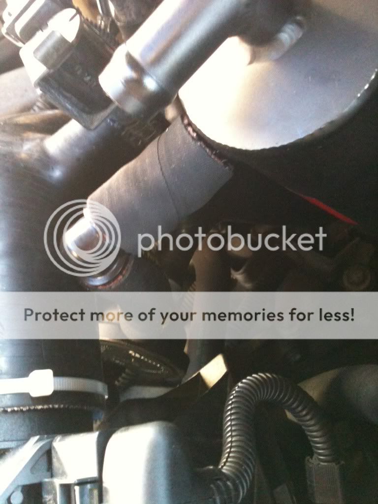
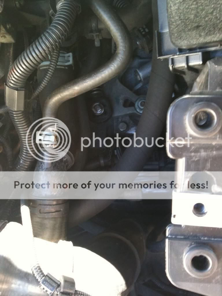
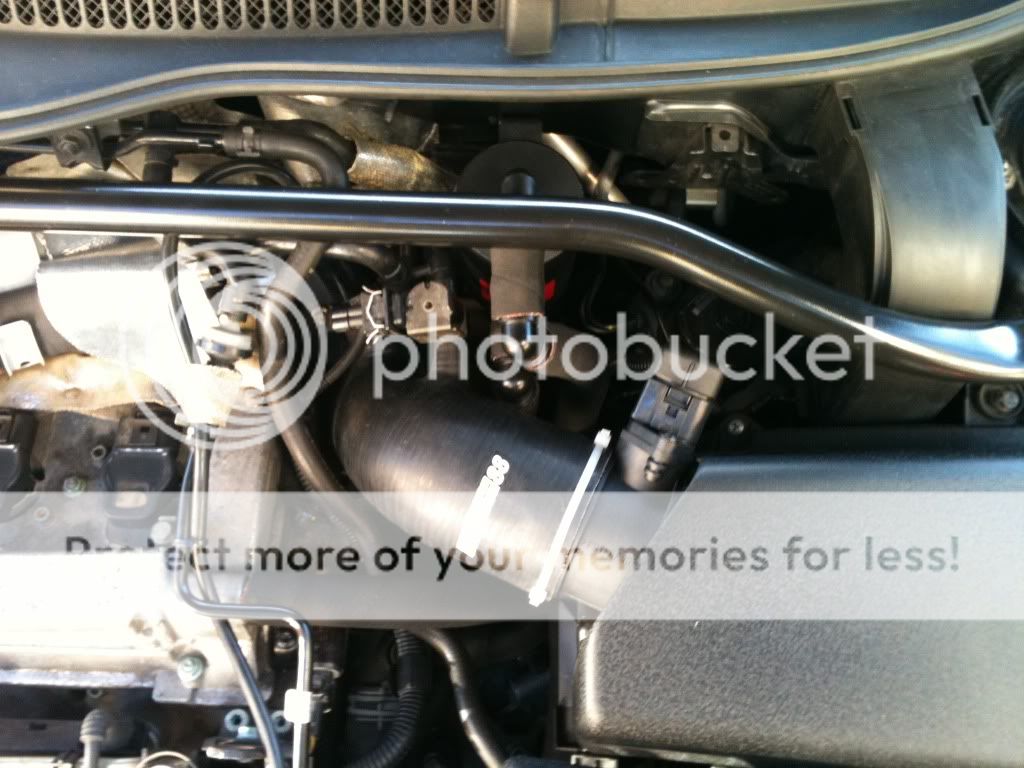
Next, use another 90 degree pipe connector to point the can inlet down under the TIP, as shown:

This will come down to the T-piece connection. Make sure you measure the length of hose right so that the T-piece is in line with the rocker breather connection.
Then cut a suitable length of hose to pipe the t-piece upto the rocker breather
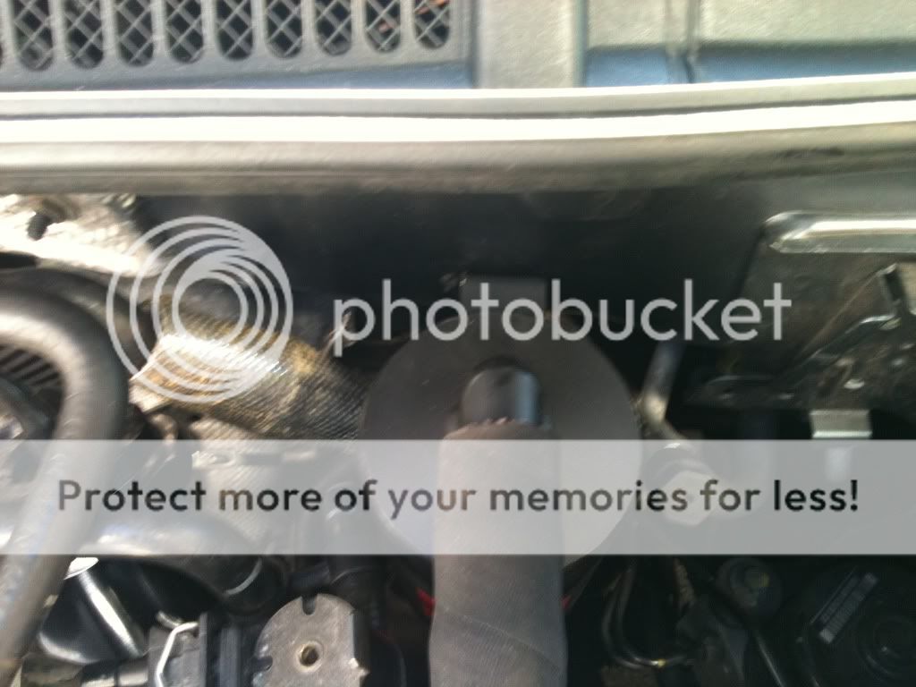
The last connection on the t-piece is then to the crank breather. There isn't much room to feed the pipe through to the breather pipe where it normally is because of the coolant pipes that are there. Therefore, when I put the crank breather 90 degree pipe back in, I pointed it outwards towards the front of the car, rather than parallel to the block like it normally is:
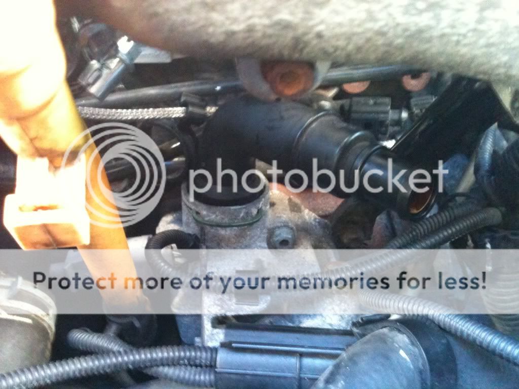
With the pipe connected, and the pipe routed underneath the throttlebody area:

Here's the finished product:
The second picture shows the relay box removed which will give access to drain the can (which I'll most likely do on a weekly basis to start with just to be safe).
Apologies for the pictures. I was in a rush when doing it so they weren't as good as they could've been.
If anyone needs me to take any more pics to make things clearer let me know :thumbsup:
Decided that I didn't want to mount it with the bracket anymore as previously shown:
And decided to have another go at getting my hand into the pollen filter flap so I could mount straight onto the firewall. Had to remove the TIP so I could drill a hole through the bulkhead. I positioned the hole about 10mm to the right and 10mm down from the right hand stud (which I had previously cut off) There are cable runs behind the firewall which come very close to where you will be drilling. All I did was hold the cables up while I drilled through. Be very carefull when doing this. Don't forget you can still mount using the bracket and left hand stud as shown on page 5 of this thread. You'll wanna use a round file to get rid of the burrs aswell afterwards.
Next was to remove this lot:
Most of you will need to remove this lot aswell, which I had already done. ( I've already written a guide for this part which includes blanking the relevant connections and fitting the brake servo feed pipe with check valve. I think it's on page 4 of this thread):
Then remove the crank breather 90 degree pipe (make sure you don't lose the green o-ring) and the PRV valve as you'll need to reuse them.
Next, attach the PRV directly to the TIP connection, in the same inlet/outlet configuration as before, just without the extention pipe. Point the inlet up towards the catch can:
This is what it looks like from the top:
You can see that all I've done is use a 90 degree 19mm pipe connection to direct the can outlet downwards. You will need to play it by ear for the lengths of hose for this, depending on your can mounting position and TIP. My Autobahn TIP connection is in a slightly different position to the oem one.
Next, use another 90 degree pipe connector to point the can inlet down under the TIP, as shown:
This will come down to the T-piece connection. Make sure you measure the length of hose right so that the T-piece is in line with the rocker breather connection.
Then cut a suitable length of hose to pipe the t-piece upto the rocker breather
The last connection on the t-piece is then to the crank breather. There isn't much room to feed the pipe through to the breather pipe where it normally is because of the coolant pipes that are there. Therefore, when I put the crank breather 90 degree pipe back in, I pointed it outwards towards the front of the car, rather than parallel to the block like it normally is:
With the pipe connected, and the pipe routed underneath the throttlebody area:
Here's the finished product:
The second picture shows the relay box removed which will give access to drain the can (which I'll most likely do on a weekly basis to start with just to be safe).
Apologies for the pictures. I was in a rush when doing it so they weren't as good as they could've been.
If anyone needs me to take any more pics to make things clearer let me know :thumbsup:
- Joined
- Dec 8, 2006
- Messages
- 12,100
- Reaction score
- 4,340
- Points
- 113
- Location
- Eastleigh
- Website
- twitter.com
haha, weekly. I emptied the catch tank on my old A3 about twice a year, and there was rarely more than half a tank full in there.....

OllieH
Registered User
haha, weekly. I emptied the catch tank on my old A3 about twice a year, and there was rarely more than half a tank full in there.....
Just wanna be safe for now until I can gauge how often it needs to be done. Some of the ukmkiv lads were emptying quite often, with a can full of oily water mix each time.
OllieH
Registered User
Mines been on 8 month and isnt even a quarter full.
Well if mines like that I'll be happy. Will be interesting to see what comes out.
- Joined
- Dec 2, 2008
- Messages
- 17,400
- Reaction score
- 1,104
- Points
- 113
Cheers for the update Ollie. I think i'll get myself a silicon TIP before I attempt this job so that the hose is made to measure.
- Joined
- Oct 27, 2006
- Messages
- 2,851
- Reaction score
- 110
- Points
- 63
Have you fitted your catch can this way then dan?You want me pop round over the bank holiday mate and show you my set up, while im there i could lend your vag-com to try and align my head lights
Also it was many many months ago when i read up on how to re align the headlights... but if somebody will explain how we can give it a try
Yeah, virtualy the same mate, the only difference is my can is located next to the battery and ive left the little vac pipe plumbed in thats under the manfiold.
Someone help out with explaining how to align headlights with vag-com please, lol.
Someone help out with explaining how to align headlights with vag-com please, lol.
- Joined
- Dec 2, 2008
- Messages
- 17,400
- Reaction score
- 1,104
- Points
- 113
Someone help out with explaining how to align headlights with vag-com please, lol.
Start a new thread, nobody will see it in here! Or you could try the search function, it's been there a while
Start a new thread, nobody will see it in here! Or you could try the search function, it's been there a while
You little bitch, lol, ill remeber that in future haha.
OllieH
Registered User
Would alot of oil in the tank in a short period of time suggest problems with the engine?
Possibly. It could mean more blow by gasses than normal which would mean piston rings aren't sealing as they should, hence more pressure in the crankcase. Or it could be as simple as the position of your can. If the can is mounted low then any residual oil in the pipes will drain into aswell, whereas if the can is mounted high (like I have) then the residual oil will drain back to the sump.