isnt there two pipes in the bottom of the S3 inlet Ollie? IIRC
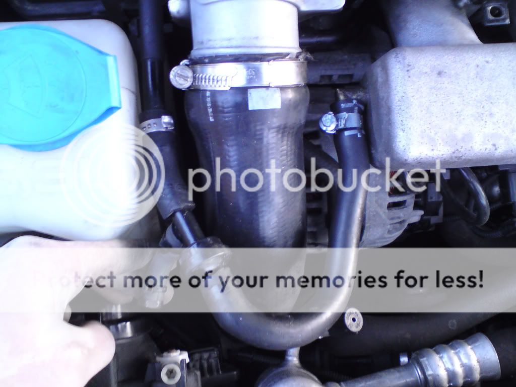
As said by jonny87 there are three. Two underside left, which have a 4mm ID, which supply a) the N249 valve/DV and b) the FPR. Shown here:
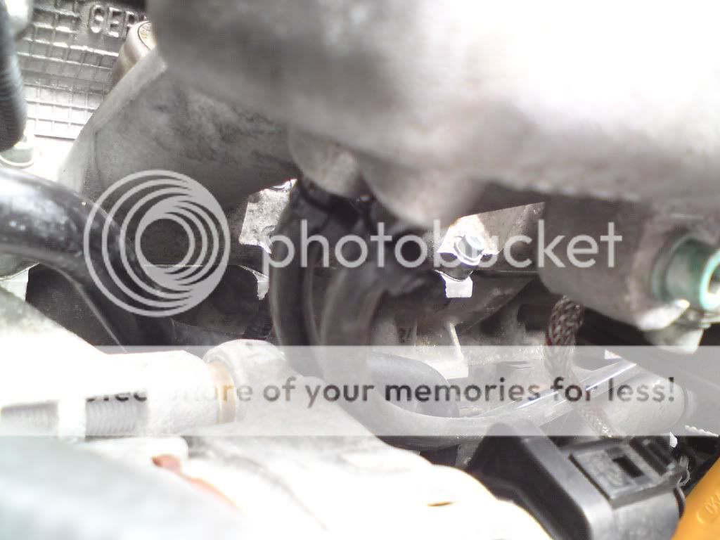
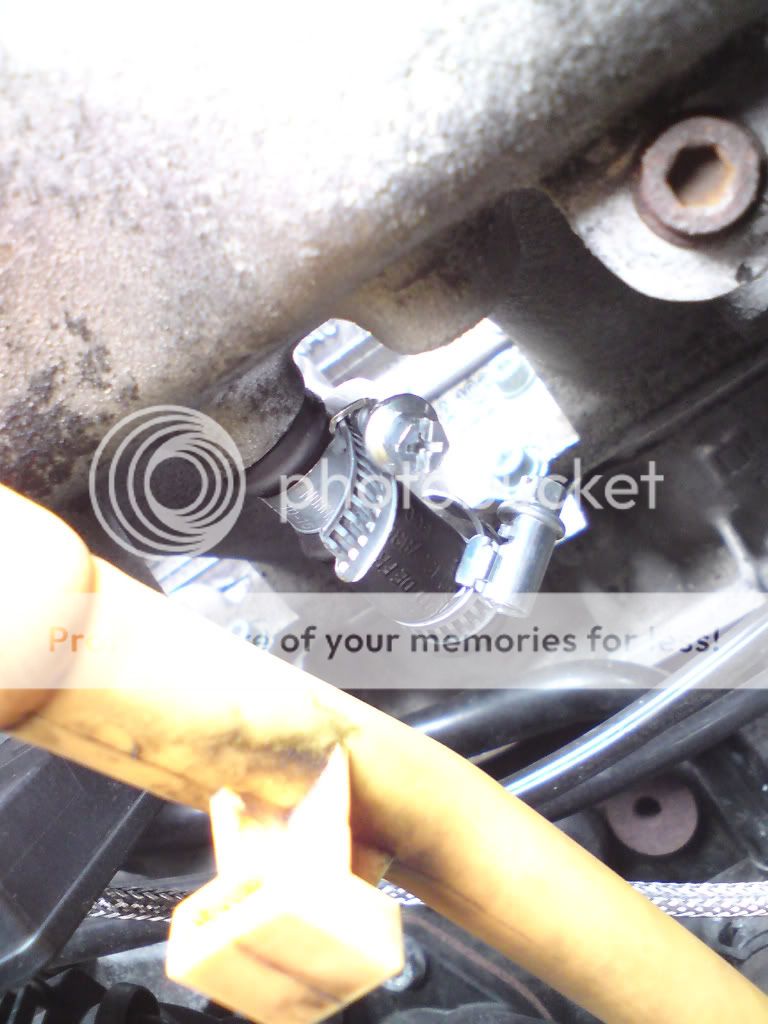
and the third one at underside centre, which has a 3/8" ID and connects to the PCV system, shown here (shown blanked on mine):
three last time i looked, two small pipes running to dv/n249 and to fpr, and a bigger hose in the centre of the underside of the inlet mani which is incorporated in this system we are replacing somehow?
on the bottom of my tip there is a hose with one of these check valves in that runs up along the top of the bulk head and back down by the chargepipe, it either leads to the inlet manifold or the charcoal chamber, is this the brake line servo thingy you are on about?
Here is a picture of the PCV system from an S3 that we'll be replacing. Orange is where it connects to the side of the inlet manifold, red is where the brake servo line connects, green is where it connects to the underside centre nipple of the inlet manifold, pink is the suction jet pump, purple is the PCV check valve, yellow is the crankcase breather, and the blue arrow is where there is normally a pipe that leads upto the rocker cover breather and then into the TIP via the PRV (hockey puck).

When you delete this system, the brake servo hose that normally connects to red, will go straight onto the side nipple that orange is connected to now (making sure you put the check valve inline, as mentioned on my earlier post). The underside nipple that green connects to now will be blanked, as I have done in the 2nd picture above. The T-piece that houses the PCV (purple) will be removed, and our new 19mm ID hose will connect straight onto the elbow pipe that comes from the crank breather (yellow). Our 19mm hose will then t-off, connecting to the rocker breather one way, and to the catch can inlet the other way. All the other parts in the above picture will be removed.
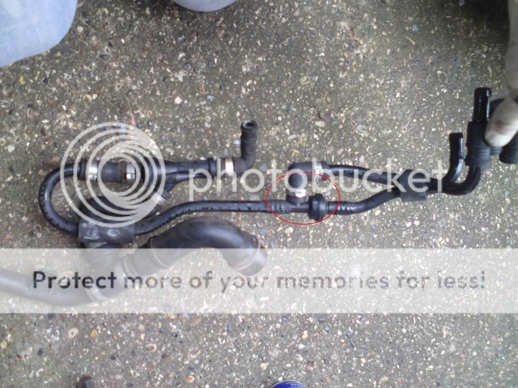
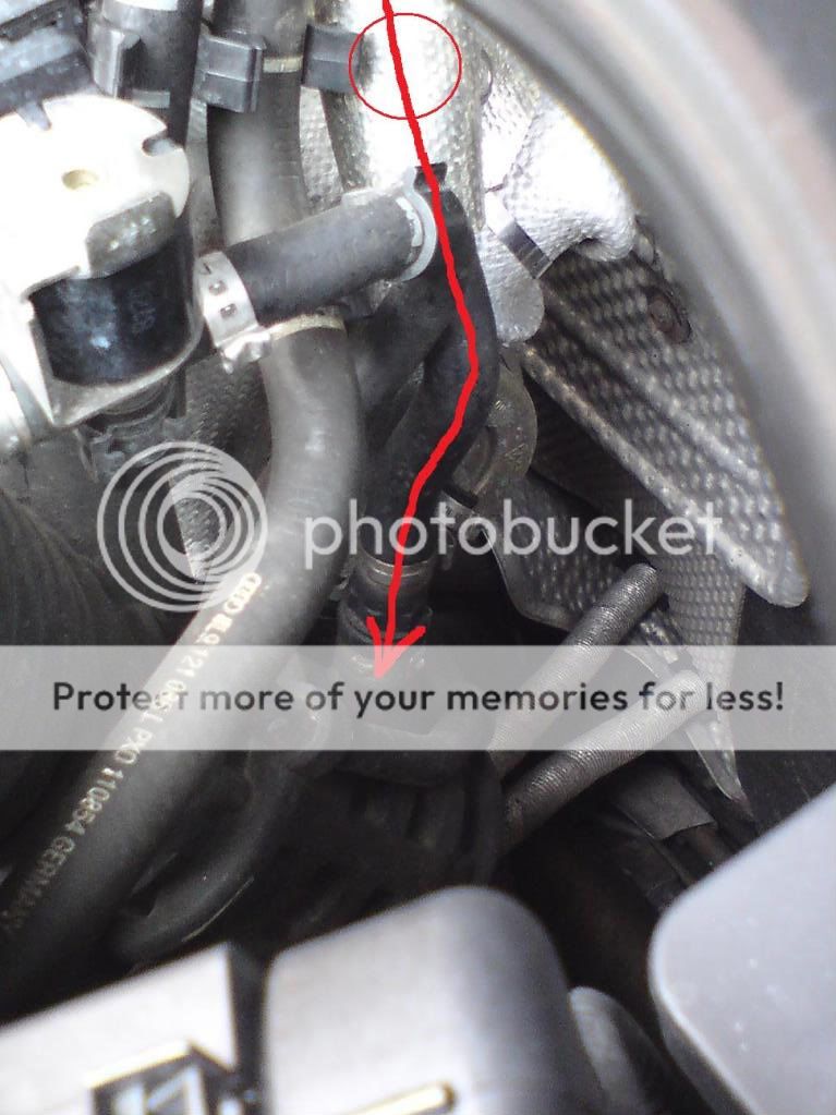
jonny87, the hose you are talking about going into the bottom of the TIP I'm assuming is this one, with the check valve shown by the circle (under the heat shielding):
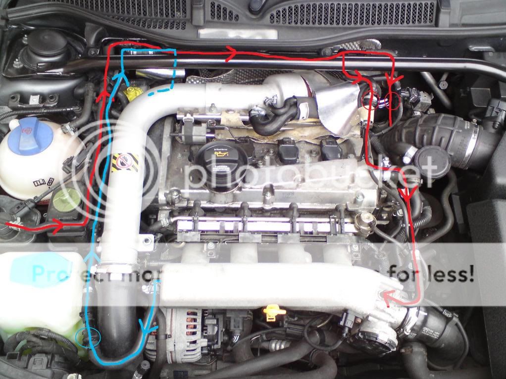
This pipe connects to the charcoal filter and also to the throttle body via another check valve. The following picture shows the route of this in the engine bay, shown in red, with the check valves circled. The blue line is the brake servo from the inlet manifold to the master cylinder. As you can see, I have already put the check valve inline (blue circle) and connected this servo hose straight onto the side of the inlet manifold (note: I have drawn the arrows on the brake servo line the wrong way round, as the inlet manifold will actually be drawing air out of the brake servo, creating a vacuum.)


") .
.