Now that I've got the car back I'm getting cracking with installing all of the parts I've bought for it. First job on the list is to install the RNSE 'G' unit & a Bluetooth 'H' module at the same time.
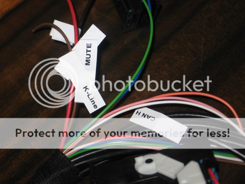
As a sense check can someone confirm that I've got my wiring instructions correct before I go splicing anything (or even start coding). Also what is the co-ax type cable from the module for, should this be joined to the RNSE aerial (see bottom pic)?
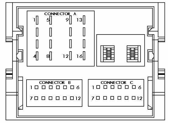
(wiring from BT unit, to...)
Red cable - pin A15
Brown cable - pin A12
Violet & Black cable - pin A11
Pink & Black cable - pin A10
Pink cable - pin A9
Grey cable - pin C12
Violet cable - pin C6
Blue cable - pin B5

As a sense check can someone confirm that I've got my wiring instructions correct before I go splicing anything (or even start coding). Also what is the co-ax type cable from the module for, should this be joined to the RNSE aerial (see bottom pic)?
(wiring from BT unit, to...)
Red cable - pin A15
Brown cable - pin A12
Violet & Black cable - pin A11
Pink & Black cable - pin A10
Pink cable - pin A9
Grey cable - pin C12
Violet cable - pin C6
Blue cable - pin B5
Last edited:


")