s3gazz's slow engine build

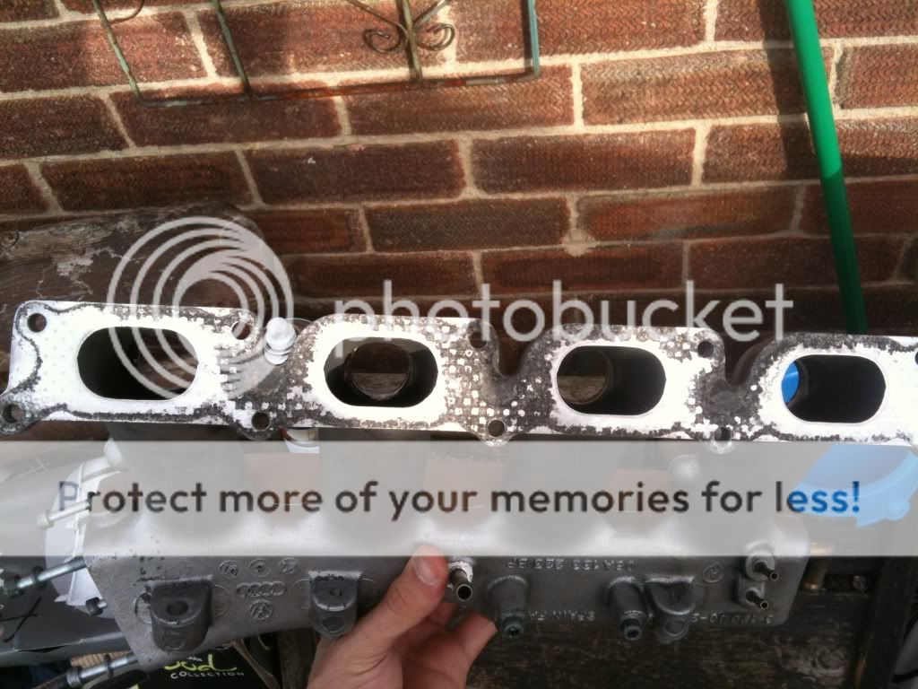
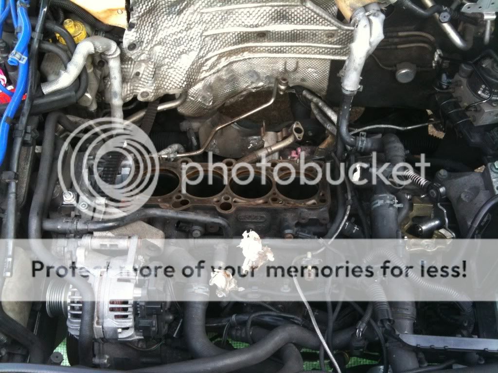
today iv swoped the cam sensor and other stuff onto the AGU head from the AMK and all new mani studs.

took the vvt off with difficulty but got there in the end just need to fit it to the AGU now. do i have to lift all the cams up
as i did on the AMK head and just drop it in and job done or is there more to it than that coz the chain is alot tighter than the AMK one thanks
 
Only the inlet cam needs to be un done to fit. You where using the vvt tool to compress the vvt/tensioner?
 
Do those cracks go through to the outside?

You know that's a copy turbine housing , not genuine?

Sure bill had another housing . Chinese copy, that had a flappy waste gate , yours is cracked there as well.
 
They don't, and I can't see any on that one, hence the remark.. Now if there are inserts then I'm mistaken but from the pictures on page 2 I can't see the inserts.
 
Gazz this is the info you need to set the cams set up

Don't worry about knocking the timing out as you need to set it up anyway when you fit the VVT

Follow the guide below the head removal part in the camshaft removal and installation


CAUTION
Cylinder head removal should not be attempted unless the engine is cold
.
1.8L Engine
1. Before servicing the vehicle, refer to the precautions in the beginning of this section.
2. Remove or disconnect the following:
* Front bumper
3. Place the hood lock carrier into the service position.
4. Turn the ignition switch to the OFF position.
5. Remove or disconnect the following:
* Negative battery cable
* Accessory drive belt
* Cooling fan
6. Drain the engine coolant.
7. Remove or disconnect the following:
* Intake manifold
* Accessory drive belts
* Wastegate bypass regulator valve
* Evaporative Emissions (EVAP) canister purge regulator valve
* Power outage stage
* Mass Air Flow (MAF) sensor
* Air cleaner housing
* Engine Temperature Control (ETC) and the temperature II sensor harness connector
* All connections from the cylinder head
* Crankcase breather line
* Oil supply line at the cylinder head
* Exhaust manifold heat shield
* Turbocharger from the exhaust manifold
* Coolant hose to the heat exchanger at the rear of the cylinder head
* Upper timing belt cover
8. Turn the crankshaft, in the direction of rotation (clockwise), until the No. 1 cylinder is at TDC.
9. Using Torx® wrench T45, loosen the timing belt tensioner.
10. Push down on the tensioner and remove the belt from the camshaft gear.
11. Remove or disconnect the following:
* Torx® bolt and swing the tensioner assembly bracket forward
* Valve cover
001-A.gif

* Cylinder head bolts, in sequence, as shown
* Cylinder head
12. Clean the gasket mating surfaces.
13. Clean and dry out the cylinder head bolt holes.To install:
NOTE: Always replace the cylinder head bolts, self-locking nuts, bolts, gaskets and O-rings.
NOTE: Refer to Section 1 of this manual for the cylinder head torque sequence illustration. The illustration is located after the Torque Specification Chart.

14. Before installing the cylinder head, set the crankshaft and camshaft to TDC for the No. 1 cylinder.
15. Loosen the turbocharger support bracket to reduce the likelihood of any tension while installing the cylinder head.
16. Install or connect the following:
* Head gasket with the part number visible from the intake side
* Cylinder head
* New cylinder head bolts, tighten by hand
17. Tighten the new cylinder head bolts in sequence in 2 steps:
Step 1: 44 ft. lbs. (60 Nm)
Step 2: additional 1⁄2 (180 degree) turn
NOTE: It is not necessary to retighten the cylinder head bolts.
18. Install or connect the following:
* Turbocharger to the exhaust manifold using new gaskets and the bolts coated with Hot Bolt Paste G 052 112 A3. Tighten the bolts to 26 ft. lbs. (35 Nm).
* Turbo support bracket. Tighten the bolts to 33 ft. lbs. (40 Nm).
* Valve cover
* Timing belt
* Accessory drive belts
* Exhaust manifold heat shield
* Oil supply lines to the cylinder head. Tighten the retaining straps to 15 ft. lbs. (20 Nm).
* Crankcase breather
* Any other items removed during disassembly
* Coolant temperature sensors
* Air cleaner housing
19. Fill the engine with coolant and bleed, if necessary.
20. Connect the negative battery cable.
21. Fully close all power windows to stop, operate all window switches for at least 1 second in the close direction to activate the one touch opening/closing function.
22. Check the oil level before starting the engine and top off, as necessary.
23. Set the clock to the correct time.
NOTE: DTCs are stored when harness connectors are detached.
24. Clear the fault codes, as necessary.
25. Install or connect the following:
* Hood lock carrier assembly
* Front bumper
26. Adjust the headlights.
Quote, originally posted by CAMSHAFT REMOVAL & INSTALLATION »
1.8L Engine
Fig. 1: Exploded view of the camshaft mounting and related components — 1.8L engine
001-B.gif

1. Before servicing the vehicle, refer to the precautions in the beginning of this section.
2. Turn the ignition switch to the OFF position.
3. Disconnect the negative battery cable.
4. Place the lock carrier into the service position.
5. Remove or disconnect the following:
* Accessory drive belts
* Engine covers
* Timing belt upper cover
6. Turn the crankshaft, in the direction of rotation (clockwise), until the No. 1 cylinder is at Top Dead Center (TDC).
7. Remove or disconnect the following:
* Timing belt tensioner by loosening it using Torx® wrench T45
* Belt from the camshaft gear by pushing the tensioner downward
* Torx® bolt and swing the tensioner assembly bracket forward
* Valve cover
* Cam gear retaining bolt by loosening it using retainer tool 3036
* Camshaft gear
* Camshaft Position (CMP) housing sensor and shutter wheel
* Hydraulic chain tensioner by securing it with bracket tensioner tool 3366Fig. 2: Do not overtighten the chain tensioner tool 3366, it can be damaged — 1.8L
002.gif

8. Verify that the camshafts are at TDC for the No. 1 cylinder. Both camshaft markings must align with arrows on the bearing caps.
9. Clean the drive chain and the cam chain gears opposite both arrows on the bearing caps. Matchmark the installed position using paint.
NOTE: The distance between the 2 arrows/paint marks is equivalent to 16 drive chain rollers and the notch on the exhaust camshaft is slightly offset inward toward the drive chain roller.
Fig. 3: To ensure proper installation, matchmark the chain-to-camshaft position — 1.8L
003.gif

Fig. 4: Camshaft bearing cap identification — 1.8L engine
004.gif

10. Remove or disconnect the following:
* Bearing caps No. 3 and 5 from the intake and exhaust camshafts
* Double bearing cap
* Both bearing caps from the chain gears on the intake and exhaust camshafts
* Hydraulic chain tensioner retaining bolts
* Intake and exhaust manifold bearing caps No. 2 and 4 by loosening them in an alternating and diagonal sequence
* Camshafts with the hydraulic chain tensioner
To install:
Fig. 5: To ensure a proper seal, be sure to apply sealant to the hatched area — 1.8L
005.gif

11. Replace the rubber/metal chain tensioner gasket and apply sealant to the hatched area, as shown.
12. Install or connect the following:
* Drive chain on the camshaft
NOTE: If installing the old chain, align the paint marks with the camshaft marks. If installing a new chain, the distance between the notches A and B on the camshafts must equal the distance between 16 drive chain rollers.
* Hydraulic chain tensioner by sliding it between the drive chain
* Camshafts with the chain tensioner lubricated with engine oil into the cylinder head
NOTE: When installing the bearing caps, verify the markings on the caps are readable from the intake side of the cylinder head.
* Intake and exhaust camshafts bearing caps No. 2 and 4. Tighten them in an alternating diagonal sequence to 84 inch lbs. (10 Nm).
* Both the intake and exhaust camshafts bearing caps on the chain sprockets. Tighten the bolts to 84 inch lbs. (10 Nm).
13. Verify the correct positions of the camshafts.
14. Remove the bracket tensioner.
15. Install or connect the following:
* Cylinder head-to-double bearing cap mating surface by lightly coating it with sealant. Tighten the remaining bearing caps to 84 inch lbs. (10 Nm).
* Camshaft gear. Tighten the bolt to 48 ft. lbs. (65 Nm).
* CMP shutter wheel and housing cover
* Valve cover
16. Align the camshaft gear and the vibration damper with the TDC markings.
17. Install or connect the following:
* Timing belt
* Accessory drive belts and the engine cover
* Lock carrier
* Negative battery cable
18. Fully close all power windows to stop, operate all window switches for at least 1 second in the close direction to activate the one-touch opening/closing function
CAUTION
After installing the lifters or the camshaft(s), the engine must NOT be started for at least 30 minutes. Otherwise the valves could strike the pistons. Rotate the engine by hand, at least 2 revolutions, to ensure that the valves do not strike the pistons.

19. Check the oil level before starting the engine.
20. Set the clock to the correct time.
21. Enter the radio security code.
NOTE: DTCs may be stored when harness connectors are detached.
22. Read the DTCs and clear the fault codes.
23. Adjust the headlights.
 
  • Like
Reactions: phil miller
That's good news in some respect, I'm guessing this turbine housing was "deep bored" rather than Bills refined porting? As it looks that way and I guess there's a lot of metal removed which won't help with heat build up and cracks.

Egt peaks on this shouldn't be any higher that a normal k04 so shouldn't crack any more but again the longer time at high EGT may not help.
 
JBS said there is no difference between AGU and AMK pistons?

There's probably a good reason you never hear them mentioned anymore....
 
Do those cracks go through to the outside?

You know that's a copy turbine housing , not genuine?

Sure bill had another housing . Chinese copy, that had a flappy waste gate , yours is cracked there as well.

Hi dan no the cracks are just inside the housing only air line but take it they will get worse no doubt.
 
JBS said there is no difference between AGU and AMK pistons?

There's probably a good reason you never hear them mentioned anymore....

Ye I asked them if they would help with performance and he said no these no difference stick with the AMK there safer lol so mind is all over in what to do now or and stay away he said if its got dept marks.
 
That's good news in some respect, I'm guessing this turbine housing was "deep bored" rather than Bills refined porting? As it looks that way and I guess there's a lot of metal removed which won't help with heat build up and cracks.

Egt peaks on this shouldn't be any higher that a normal k04 so shouldn't crack any more but again the longer time at high EGT may not help.

Hi dan what u mean mate bu deep board to refind porting should I ask them to do something to it to help egt's pal
 
Only the inlet cam needs to be un done to fit. You where using the vvt tool to compress the vvt/tensioner?

I used the tool dan ye but I took it out the wrong way exhaust side cams up still would not move so lifted the lot and the put em back and tightened em back up now need to fit vvt to the AGU I'll just lift the inlet side then.

Did not want to put the cams back in different to how they are now as the highdrolics push out.
 
Thanks Andrew I'll get this done this week and have the pistons out too.
If the marks don't line up now do I just put them back to how they are
 
bit of an update head complainted just waiting on my v3 xs mani to come so i fix it to the head new downpipe sports cat too.

received pistons off dani thanks mate pics to come of the head, pistons.

IMG_0494.jpg


IMG_0493.jpg


IMG_0491.jpg


IMG_0489.jpg


IMG_0487.jpg


IMG_0488.jpg


can i sort these out with wet and dry thanks just i want to get my new piston rings in them thanks
 
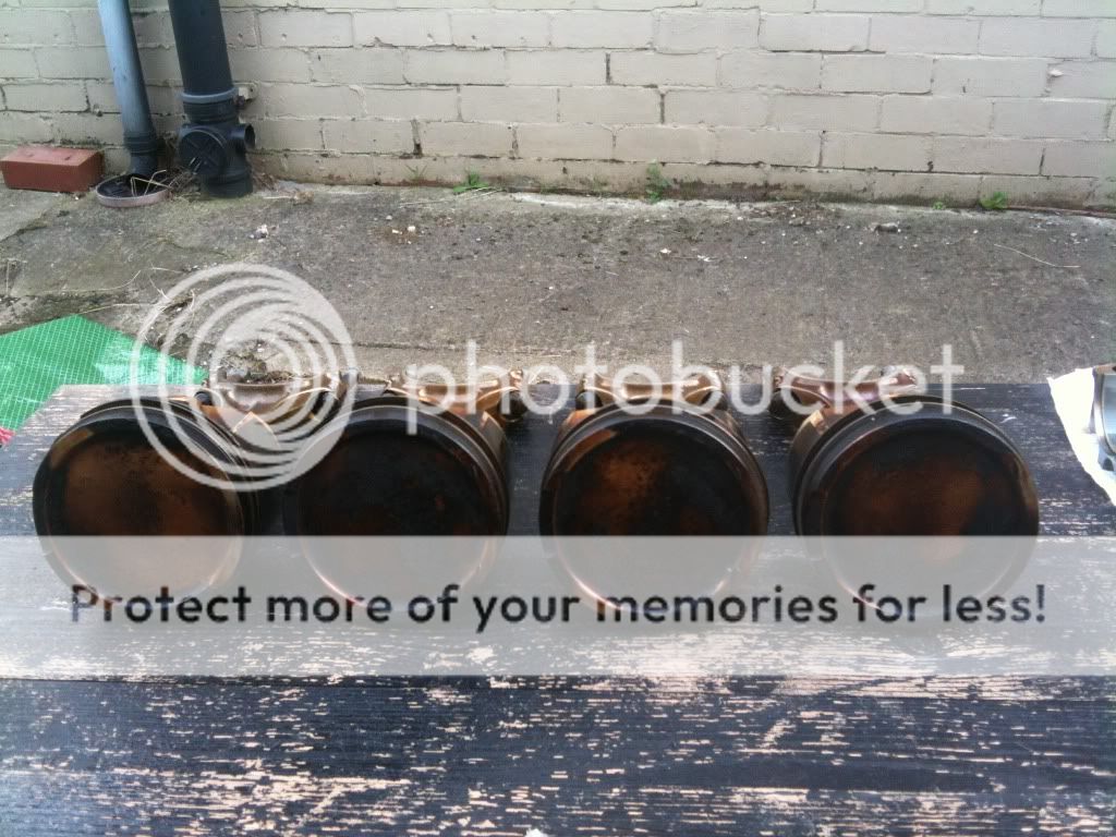
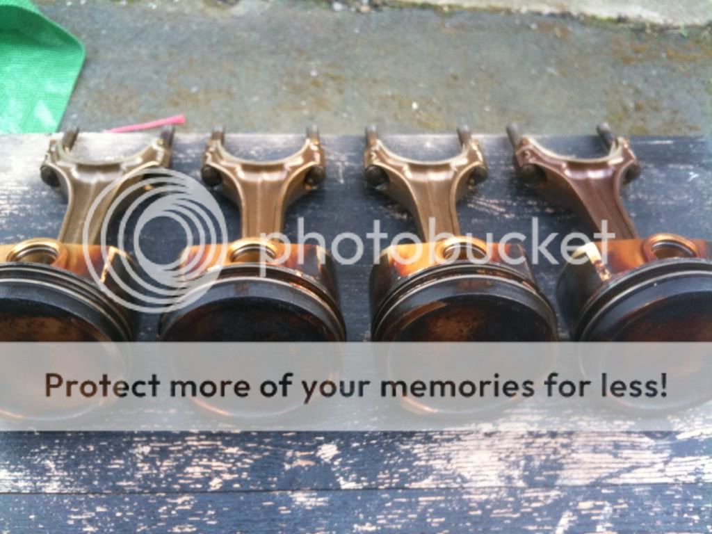
It seems somewhat normal to have some marks on the pistons, i've stripped three stock AEB motors and they all had "dots" on the crowns. Yours do seem particularly bad though, with heavy concentrations of dots on most of them.

Pic from my own engine:

DSC_0143.jpg
 
Hmmmm. Mine from the 108k agu were perfect. Will pull the 216k engine apart at the weekend and compare :)
 
Hmmmm. Mine from the 108k agu were perfect. Will pull the 216k engine apart at the weekend and compare :)

i can second this, mine were sound from my 102K agu.

how deep are the det marks? surly they would be okay with a sand down (not that i know what im talking about)
 
hi all sorry to jump a thread but where is the best place to get the VVT tool from?
 
Yours certainly look far worse than mine did. Yours have concentrations of pitting near the exhaust valves on 3 of the four pistons, and big dings out of the last one. I think you'll struggle to sand those out...
 
my pistons before i cleaned em


IMG_0428.jpg


IMG_0432.jpg


IMG_0430.jpg


IMG_0422.jpg


IMG_0420.jpg


IMG_0418.jpg


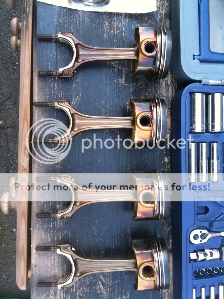
heres my pistons cleaned up


IMG_0449.jpg


IMG_0451.jpg


IMG_0456.jpg


IMG_0452.jpg


IMG_0454.jpg


IMG_0459.jpg


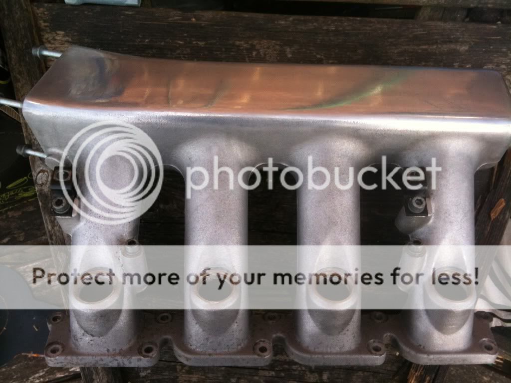
and some of the inlet mani


IMG_0445.jpg


IMG_0444.jpg


IMG_0447.jpg


IMG_0446.jpg
 
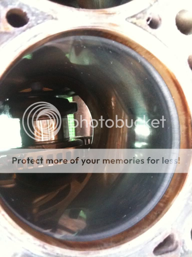
pics of my bores and crank

IMG_0410.jpg


IMG_0390-1.jpg


IMG_0408.jpg


IMG_0405.jpg


IMG_0412.jpg


IMG_0411.jpg


IMG_0413.jpg


oil pumps in comparison


IMG_0401-1.jpg


IMG_0396-1.jpg


IMG_0399-1.jpg


IMG_0400-1.jpg


after all this was done andrew very kindly deglazed my bores for me thanks so much mate all set to be put back together now when parts turn up that is
 
I normally centre punch dots on the bottom of the pistons to mark what cylinder they were from... have you marked yours up? usually good practice to put the pistons back in the same holes they came out of...

The pistons with the valve marks on... the marks still look raised... I would be looking to sand those flat mate

<tuffty/>

ye tuffty iv marked them mate put numbers on them.

iv not yet desided on what to do with the AGU ones so when iv made mind up ill sand em down andrew is going to have a look at them for me pal really do want to AGU ones tho
 
had some help this weekend makeing shore my piston rings were with in tolerance by andrew and there where.
i followed bills post wich says they need to be

0.016 top
0.018 mid
0.016 bot

the following readings were what andrew got with a feeler gauge

top 0.017 fit in the gap
mid 0.020 fit in tight
bot 0.017

should this be ok now just to fit them to my pistons tommorow ready for the rods to turn up thanks.
 
So then some news lol rich said my ECU is fooook ed the chip is damaged its running lean and hot so need a new ecu found one for £50 so ill have that sometime this week. rich has done a bass map too and that's all I no for now.
 
So then some news lol rich said my ECU is fooook ed the chip is damaged its running lean and hot so need a new ecu found one for £50 so ill have that sometime this week. rich has done a bass map too and that's all I no for now.


But didn't you replace the ecu already?

So the new ecu you got is also faulty? Or is this the original one?
 
But didn't you replace the ecu already?

So the new ecu you got is also faulty? Or is this the original one?

i did not replace the ecu I gave u dan still the same one. But iv got another for £50 sending it straight to Rick
 
i did not replace the ecu I gave u dan still the same one. But iv got another for £50 sending it straight to Rick


Not sure I follow.. You knew it was knackered 2+ months ago! ..Rick has only confirmed what you knew already surely?
 

Similar threads