Hybrid turbocharger k04 build

BALANCING:

And I don't mean trying to stand up straight after a night on the booze!

Probably one of the most important parts of building any turbo is to ensure the rotating parts are properly balanced. This is critical to ensure the long life of the turbo and also to make sure it runs quietly.

So what do I mean by unbalanced? Well it's basically and excessive amount of weight at a given radius. Turbo balance is expressed as milligrams inches, Ie if you took a perfectly balanced turbo and put 1 milligram at 1 inch on a blade it would then be 1 milligram-inch out of balance.

There are 2 types of balancing techiques, the first is component balancing and the other is assembly balancing.

Component balancing is literally the individual balancing of the main rotor parts. These are the turbine shaft and the compressor wheel. It is critical that these items are balanced, Items such as the nut and thrust spacer are not required to be balanced as they are machined at manufacture to specific limits well within the spec of a balanced turbo. However, when all these items are put together a certain amount of new unbalance is created and this is called "stackup" Literally meaning stacking up all the components unbalance "milligram-inches" together to make a combined milligram-inch unbalance.

Stackup balance isn't really a major concern as the turbine and compressor wheels are balanced well within the tolerance needed for an assembled turbo, so even by adding the nut and thrust spacer the stackup balance is still well within limits required for the turbo and wont cause a problem.

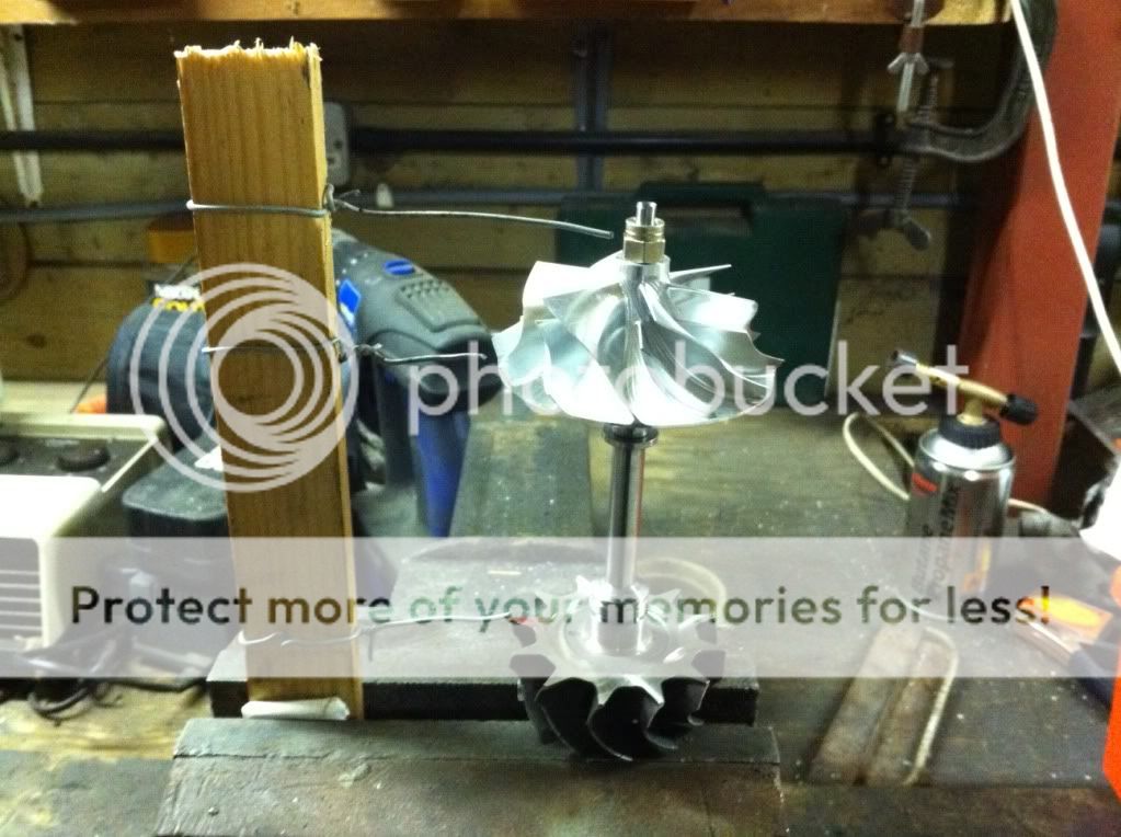
Unfortunately with small turbo's, the light mass of the components and high speeds it isn't sometimes enough to balance the components and allow for stackup balance and an effective way to overcome this is to trim balance the components. This is basically taking the complete rotating assembly: turbine, compressor, nut and thrust spacer and balancing it further to over come the stackup balance.

Here is a picture of a trim balance.

photo-36.jpg


While this method is great for balancing a turbo, it still requires the turbo rotor to be dismantled and reassembled in the CHRA after the balance has been completed. Marking up of the components is critical and correct assembly is also vital. This is the method that is being used in my turbo builds, and with a little skill and a steady hand very good results can be achieved this way. The main plus point of this method is that it is considerably cheaper and for the small time builder offers the best way to achieve a balanced unit. And from having spoken to well known turbo builders they have used this method very successfully in their builds. I would also like to thank Slappy-Dunbar as well for some very useful information he provided and almost being gracious enough in sharing it. I know many of turbo builders wouldn't have, trade secrets and all that nonsense!

The other type of Balancing is the CHRA balance, this can be done in 2 ways the VSR ( vibration sort rig ) or low speed ( balancing Machine)

The VSR machine is EXPENSIVE! You basically place your unbalanced CHRA assembly in the machine, and it spins the turbine wheel at high speed, Oil is fed to the journals and the machine senses the vibration. The computer then tells machine operator where it is unbalanced and he will grind small amounts of metal off the nut or nose of the compressor wheel to bring it into balance. The only down side of the VSR is that it is only a single plane IE just the compressor is worked on to achieve balance, it does have the advantage that as it is spun at high speed and any noises or oil leaks can be found easily.

The Balancing machine or Low speed rig again balances the complete CHRA but this time does so at a relatively low speed normally belt driven. No oil is needed and 2 Planes can be balanced Ie turbine and Compressor, offering a more accurate balance in theory

Either way will eliminate the stackup balance as well/

One thing definatly worth noting is that, balancing a turbo at high RPM doesn't give you a better balance than balancing it at slow rpm... Confused??? Remember we are talking about a weight at a given distance! 5milligram - inches at 1000 rpm is still 5milligrams - inches at 100,000 rpm, the weight hasn't change but the force has. The most important factor in balancing is to have a machine that is accurate for it's given speed. It's better to have a machine more accurate at 1000 rpm than one less accurate at 100,000 rpm.

So why choose VSR over Component or trim balancing? well the simple answer is cost and time.

A VSR machine is very fast and efficient way of producing mass produced items accurately. CHRA's can be put together quickly, with no need to take special care in assembly, the balancing is all done in one go and the item is finished.

Trim balancing can offer a more accurate balance due to the 2 plane balance but relies on human skill to balance, assemble, trim balance, disassemble and reassemble in the CHRA. For a manufacturer or large turbo builder this is time consuming and impractical, but for the bespoke builder it is ideal as balancing costs are reduced and varying spec'd turbos can all be built separately with out the need for expensive VSR machines.

I hope this has covered it and helps put some peoples minds at rest who may think that component balancing is an inferior technique to VSR.

Here's a picture of a VSR machine. There are also plenty of youtube clips on VSR, Trim and Component balancing if your that way inclined ;-)

photo-35.jpg
 
Last edited:
  • Like
Reactions: Pedrosousa
Been sitting down with a cuppa reading through this thread and it's really good!
prior to this I had little or no knowledge of turbos, rebuilds, hybrids etc but the thread is proving very informative and good learning!

So apologies if I'm jumping the gun here slightly, but what do you reckon the cost comparison (roughly) would be between buying the parts and doing a hybrid yourself and paying a 3rd party to buy the parts and build for you?

Personally I would have a company (or individual) do it for me as my mechanical engineering expertise is non existent and I'd be mortified if I destroyed my S3!
 
Phew! Stooopid iPad just closed safari as I pressed 'post quick reply'...thought I'd lose my post.
iPads are awesome but also very frustrating when they throw a tantrum...kinda like my Mrs...
Anyway!
Great thread. Looking forward to more!
 
Been sitting down with a cuppa reading through this thread and it's really good!
prior to this I had little or no knowledge of turbos, rebuilds, hybrids etc but the thread is proving very informative and good learning!

So apologies if I'm jumping the gun here slightly, but what do you reckon the cost comparison (roughly) would be between buying the parts and doing a hybrid yourself and paying a 3rd party to buy the parts and build for you?

Personally I would have a company (or individual) do it for me as my mechanical engineering expertise is non existent and I'd be mortified if I destroyed my S3!

Buying the parts and doing it yourself is definitely cheaper, I haven't completely finished yet but even a build with all new parts bar the exhaust housing will come in at 50% the cost of a bought one! However, there is 1 major point which you make and that's having confidence in the final product and it not falling apart weeks/months etc down the line. Installing a hybrid generally means the engine/turbo are going to be put pressures and torques above the original engines spec. So it will never be a case of building your hybrid and running 10psi and 225bhp. It's going to get tested and possibly driven at 23psi+ and 6800 rpm! I have no reason why mine won't work successfully but until it's tested I'll never know for sure. You admittedly pay for the hybrid builders experience when you buy one over the counter. However, as I hope to show if you have abit of knowledge, know how to use a spanner and some skill there is no reason that with a bit of patience and the right parts you can successfully build your own hybrid for the same money as 2nd hand unit.

If you can remove the turbo off an s3 you can build a hybrid. It's no more technical.

I've nearly finished the dissambley guide and there you'll see how in depth or not a turbo rebuild is or isn't!
 
  • Like
Reactions: stevewushu
I would imagine you should expect to pay somewhere in the region of £600-800 for a hybrid built by one of the well known turbo builders, depending on the exact spec ofcourse.
 
I bought a Cr hybrid a year ago and had nowt but surging probs anyway every tuner iv spoke to said get rid and buy something elso as they don't think I'll get over 300bhp and have surge prob still after mapped now iv got sell on my mind for someone elseies hybrid turbo with non of the crappy problems
 
Who mapped it?

These turbos are all made from the same components, so the only way to get rid of surge without changing the rest of the installation is to fit a smaller hybrid.

Cant you just run a bit less boost around the area where its surging?
 
Rs tunning are going to map it after Christmas pal but it's on standered map now as the crapy map I had on it was running full boost at 24 psi about 3500 rpm
 
I'd imagine if you just pulled the boost back a bit, maybe 18-20psi, then tapered it in as the revs climb you'll get past the surge.
 
IIRC, the sweet spot is 22 psi, . it's then mapped so the request stays around that level from as soon as its fully available till the redline. If its left to spike at silly levels the surging occurs. At least thats how i understand it.
 
Been sitting down with a cuppa reading through this thread and it's really good!
prior to this I had little or no knowledge of turbos, rebuilds, hybrids etc but the thread is proving very informative and good learning!

So apologies if I'm jumping the gun here slightly, but what do you reckon the cost comparison (roughly) would be between buying the parts and doing a hybrid yourself and paying a 3rd party to buy the parts and build for you?

Personally I would have a company (or individual) do it for me as my mechanical engineering expertise is non existent and I'd be mortified if I destroyed my S3!

info shared with folks here> k04 Hybrid for 210/225 owners, LCR/TT/S3 etc-330bhp achieved!! - SEAT Cupra.net - SEAT Forum
and here> k03 hybrid PLUS now here. Lupo 1.8t demo/test mule-Now Running! - SEAT Cupra.net - SEAT Forum
and here> hybrid K04 + 3inch TIP + hi-flow Discussion Thread. - SEAT Cupra.net - SEAT Forum

Additional to this, and found by slappy, his "surge" noise was cured by adding springs to his DV, and the noise made was on his the DV popping off its seat and not surge at all..... something to consider.
 
Will have go at the dv spring see what happens as for mapping hopefully will sort the surge out by dropping the boost a bit
 
which is what we did with barks hybrid

I'd rather the OP addressed the surge question only when/if circumstances require it. I've said this before and I still believe it: clipping turbine rotors is a lousy way to make a turbo work. He should keep that rotor intact and preserve spool and responsiveness.
 
I'd rather the OP addressed the surge question only when/if circumstances require it. I've said this before and I still believe it: clipping turbine rotors is a lousy way to make a turbo work. He should keep that rotor intact and preserve spool and responsiveness.

barks is unclipped... you have the logs I sent you..
its progressive and graduated boost, skirting around the surge noise....

lupo is clipped.. no surge, no lesser spool either when overlaying plots
 
barks is unclipped... you have the logs I sent you..
its progressive and graduated boost, skirting around the surge noise....

​I think a solution in-software is by far the way to do it, Bill. Keep the wheels intact and shape the boost profile to suit the motor's capacity. And by the way, I'm back to thinking this sound is surge. I can't get rid of it with just a DV or other mods. Rats.
 
​I think a solution in-software is by far the way to do it, Bill. Keep the wheels intact and shape the boost profile to suit the motor's capacity. And by the way, I'm back to thinking this sound is surge. I can't get rid of it with just a DV or other mods. Rats.
boo, thats a shame.. was a nice thought tho none the less
 
Sorry if this is a silly question, but, DV???
 
So a little update is needed.

Well mixed fortunes really.

I dropped off 3 sets of housings to the machine shop, 2 of the where k04 and the other one was a k03s, 4 weeks ago! Due to the machine shop being busy they didn't managed to start the work till Xmas, then Xmas came and then the flu! So basically this morning I picked up the housings. Good news was that the new k04 housings and k03s exhaust housing got done but the other k04 ran into a problem! Although it looked ok when I dropped it off there was a small hair line crack that appeared during the maching, a pain! I ended up legging it back home to get another one I had lying around as I had promised this one to an ASN member , who had understandably been waiting patiently for weeks!

Any way my new housings look spot on and the end result is this..

photo-42.jpg


A all new part k04 hybrid.. Home made and looking very nice..

I have in the process of putting it together compiled a how to dissamble and how to rebuild your turbo. For the sake of the K03 people the dissambley is with a k03s and the assembly is the new K04 hybrid... I did this as I had a k03s to take apart and the hybrid to build. In essence they are identical and therefore no different in either procedure.

I will post these in the next few days.

On another note I purchased an s3 today. I've been on the look out for the right one for a couple of months, I've seen so many, ones that have been clocked, ones that have been insurance right offs. Over priced, spares or repairs and some just not fit for the road, but yesterday the right car came up.

A W reg 64k 2 previous owners. It's had 7k spent on it in the last 2 years on performance upgrades including Porsche brakes, rs6 alloys, downpipe, and blue Haldex controller. Fmic and revo stage 2. Basically bar the rods,map,manifold and injectors everything I need to fit the hybrid, everything already done and far cheaper than I could have ever done it for.

So welcome my 3rd s3 and hopefully the one that proves my hybrid works :)


With regard the k03s I got machined, plan is initially build a k04-001 equivalent ie k03s comp wheel and k04 exhaust wheel and then a k03s hybrid with k04 internals and k04 compressor housing, I am tempted to build one using the same 2283 comp wheel as it'll work out the same price but pretty sure the k03s exhaust will just be too restrictive! Running before I can walk springs to mind!!!!
 
Hi BB, well done in your purchas of another s3, put some pics up when you have time. And its nice to see your getting round to the how to guide as it will be some intresting stuff. Out of intrest and stupudity lol, in regards to the k03s being restrictive, would there not be some kind of milling pattern that could be ingraved into the housing to reduce the turbulance ie like a grooved effect, in essence to channel the flow? So not taking as much flesh out but increasing the surface area also? (it sounds good in my head lol)
 
Hi BB, well done in your purchas of another s3, put some pics up when you have time. And its nice to see your getting round to the how to guide as it will be some intresting stuff. Out of intrest and stupudity lol, in regards to the k03s being restrictive, would there not be some kind of milling pattern that could be ingraved into the housing to reduce the turbulance ie like a grooved effect, in essence to channel the flow? So not taking as much flesh out but increasing the surface area also? (it sounds good in my head lol)

Funny you should mention that! In one of my earlier posts I mentioned I was going to modify the exhaust outlet to help with the surge and your suggestion is precisely what I plan on doing. A series of shallow channels even spaced along the exit to smooth the air flow. Its much the same as having the larger opening as used by some hybrids but with the added benefit of creating a smoothing effect. You get the same area increase while reducing the turbulent flow. There are to types of flow, laminar and turbulent. We can't change or help the laminar flow As we would need to change the makeup of the gas to do this! But we can change the turbulent, basically small eddies that occur in the flow of the exhaust gasses. You've heard of port and polishing, well polishing reduces the turbulent flow so increasing flow rates. There is a trade off though of increasing surface area, which In turn creates more surface friction and more turbulence and creating the grooves/channels which guides the air better and reduces the amount of turbulence that can occur. The secret is to create these grooves while ensuring they are as smooth as possible also to polish as much of the inside of the housing as practical to reduce friction.

While your idea is good (in your head) just creating the grooves on there own increases surface area which creates more drag area and as a result more eddies,back currents..


All this said, in jet engines a series of stators and vains are used in the engine to smooth out the airflow, which reduces the likely hood of surge. While we are using these we are smoothing the air flow out which will in turn help reduce surge.

It like the turbo will ba try it and see thing but certainly something I will be doing, however ever like Bill pointed out, no point in trying it until we know it occurs!

Bill, I was aware this had been done and had seen a few posts on audisrs.com about but never seen any results on comments, but to be honest it was just a thought at the back of my mind, but would be very interest to read anything that has be done on the subject, especially as to build one would cost nearly the same as a k03s/k04 hybrid, crazily enough!
 
...Bill, I was aware this had been done and had seen a few posts on audisrs.com about but never seen any results on comments, but to be honest it was just a thought at the back of my mind, but would be very interest to read anything that has be done on the subject, especially as to build one would cost nearly the same as a k03s/k04 hybrid, crazily enough!

I think what Bill means is he has already built a K03 turbo with a 2283 comp wheel... its currently sat in Mrs B's Lupo producing just over 300hp at 20 ish psi...

<tuffty/>
 
I think what Bill means is he has already built a K03 turbo with a 2283 comp wheel... its currently sat in Mrs B's Lupo producing just over 300hp at 20 ish psi...

<tuffty/>
Cool, that's even better it's been done by someone on here. I totally appreciate that everything has probably been done before and I'm not really inventing anything new, it's just seeing whether its all possible, having the confidence to do it yourself and actually making it work. It won't happen for a while though as need to concentrate on the k04 and k03s mk1 first!
 
Cool, that's even better it's been done by someone on here. I totally appreciate that everything has probably been done before and I'm not really inventing anything new, it's just seeing whether its all possible, having the confidence to do it yourself and actually making it work. It won't happen for a while though as need to concentrate on the k04 and k03s mk1 first!

I have previously posted the links to it in this thread. you maybe missed them nor not had chance to read..
here> k03 hybrid PLUS now here. Lupo 1.8t demo/test mule-Now Running! - SEAT Cupra.net - SEAT Forum

along with mods it required to fit into a K03 position.
EGT's and manifold pressure have been logged...
No hotside mods to it (yet), stock wastegate size also.. 7 degree clip on turbine tho to avoid surge, which it achieved.
 
How to dismantle your K03/K04 turbo. Here is the guide i have produce in order for anyone who fancies ago. I would like to think it covers everything and flows in order and is pretty self explanatary. I know I say this as I have done it numerous times but it isn't that hard and providing you follow the steps should be pretty straight forward. The rebuild is pretty much the reverse. However I will post a full guide as there are a couple of things that need to be covered which aren't here.

Tools required
10mm spanner
10mm deep socket
8mm spanner
Big flat head screw driver
Hammer
Mole grips
Insulating tape
Vice
Homemade tool… See number 7

Time required 30-45mins

How to:
1) First we have to make a few markings on the turbo; this will help us line everything back up once we have taken the turbo apart. It will ensure the housings are put back together correctly and thus the entire oil pipe, water pipes etc line up once installed. In order to do this take your marker pen and place a line across the compressor housing, back plate and CHRA. Then do the same on the exhaust housing and CHRA at the other end. Using a piece of insulating tape, mark the actuator shaft below the top bolt, holding the bolt in place and showing where it is located.
photo-55.jpg

2) Now place the turbo in the vice so that the CHRA is in the vertical position. The picture above shows the tape in place and also the turbo mounted in the vice. The K04 is easier as you can use the exhaust studs to hold the turbo in the vice. Once secure remove the bottom bolt on the actuator shaft with the 10mm deep socket or spanner, if you find the shaft spins just hold it with the mole grips, try not to use the other bolt as this the one that sets the pretension and you don’t really want to change this unless you need, to calibrate or have to.

3) Remove the bolts on the compressor housing clamping the housing and back plate together. The K03 has 3 bolts on the actuator and 2 on the C clamp whilst the K04 has 2 on the actuator bracket and 2 for the C clamp.
4) If you are lucky the compressor housing will separate from the turbo by simply lifting it off. However when these are built, sealant is used to seal the back plate and comp housing so it may require a gentle tap on the housing to separate the 2. In order to do this I suggest you tap upwards, on the bolt hole lugs in sequence around the housing. It should come apart pretty easily anyway so there is no need to WHACK it!!
photo-54.jpg

photo-53.jpg

5) In order to separate the CHRA from the exhaust housing we need to rotate the small tabs located on the exhaust housing. The bolt holding these in place, for some reason is about a 9.5mm bolt… Why?? I have no idea! They are almost impossible to remove with a spanner, as a 9mm doesn’t fit and 10mm rounds the heads, plus there is limited room anyway. So the easiest way by far is to use your large flat head screw driver and the hammer and gently knock them round to achieve this. As they are off centre lugs by placing the blade of the screw driver on the part nearest the CHRA you can knock them anti-clockwise and spin them out of the way. They should when done look like this.
photo-52.jpg


6) Once you have all the lugs as above, you can now separate the CHRA from the exhaust housing. If you are lucky again, the CHRA will lift out of the housing with a little help, however I doubt it’ll be that easy, so gently heat the exhaust housing and then tap the CHRA under the back plate upwards and the 2 will come apart. Make sure you hit the cast iron of the CHRA and not the back plate itself.. Very Important!!!

7) We now have a separated CHRA from the housings. In order for use to strip down the CHRA we need to make a little tool to enable us to re-align all the internal parts exactly the same way when we come to rebuild it. If however you are using new parts for your rebuild/hybrid then just skip this step but you will still need to make one of these so it’s worth reading.
The tool I have made was done by using a 1” by 0.5” piece of wood 20 Cm long with 3 medium gauge wires attached. As shown
photo-57.jpg


It’s nothing fancy but it works and if you take your time using it then you will get very accurate results providing you mark up and re-assemble correctly.

The purpose of the tool is to enable you to mark the turbo shaft, compressor and Nut, dismantle and rebuild exactly the same, thus ensuring the balance of the turbo is kept. There is no reason why if followed correctly the turbo shaft will become unbalanced. It may look heath Robinson, but it works very well.
So to make use of this tool, place the CHRA in the vice. You will notice that shaft end has 6 sides, clamp the shaft in the vice so the faces of the shaft end lie flat against the vice sides. Then place the tool alongside the CHRA as shown above so the 3 wires roughly line up with the exhaust wheel, compressor wheel and Nut. If you can try and get one of the turbine blades to line up down the centre line of the vice opening, it’s not essential but helps and clamp the both tight in the vice. Mark the turbine blade closest the to vice centre line, a compressor blade the same and the nut. Now move the bottom wire so it is pointing or touching the turbine blade, do the same for the compressor wheel and finally the nut.
It should look like this, the nut has been undone here but you can see the red markings on the compressor wheel and turbine wheel
photo-58.jpg


Check and double check all the markings and wires to ensure it all lines up and is marked clearly. Once you are happy, undo the vice slightly and tilt the tool backwards out of the way. Tight the vice again and undo the Nut on the shaft.

THIS NUT IS A REVERSE THREAD NUT… TURN IT CLOCKWISE TO UNDO AS IF YOU WHERE TIGHTENING IT.. IT’S A REVERSE THREAD NUT………..
If you try and undo it as normal you will snap the shaft!! You have been warned.
8) Once the nut is off, remove the compressor wheel, it should just twist and lift off, be careful of the blades as they are sharp! IF it is really stuck as gentle heating of the compressor wheel will lift it off easily. Then the back plate with the thrust collar in the centre will lift off as well
9) You should now be left with this
photo-50.jpg

In this picture you can see the oil thrower, thrust bearing, thrust washer,

photo-49.jpg

And in this picture below that you can see the C clip holding the bearing and bearing locator.
All these need to be removed. In order to remove the C clip holding the bearing and locator, simply use a flat head screw driver on one of the ends of the C clip and flick it out. It only sits in a shallow groove in the housing so pops out easily. The bearing can be removed by removing the CHRA from the vice, turning it upside down and tapping it. It should just drop out. At this point it is worth removing to the line-up tool and putting it somewhere safe where the wires aren’t going to get bent or moved, preferably leave it in the vice, ensuring the wires don’t get moved is the key part to lining it all up again correctly!
10) To remove the turbine shaft, simple hold the CHRA in your hand and pull the shaft out, you may need to move the shaft up and down IE from 12pm to 6pm a little bit it should just pull out.
11) Finally, back to the back plate, separate the thrust collar from the back plate by pulling it out of the back plate in much the same way as the turbine shaft from the CHRA, in an up/down motion or by pushing out from the front of the back plate.
Once you are complete you should now be left with a bench looking like this
photo-46.jpg


There will be
Exhaust housing
Compressor housing
Shaft nut
Compressor wheel
Back plate
Thrust collar (with Seal)
Oil thrower
Thrust bearing
Thrust washer
C clip
Bearing Locator
Bearing
CHRA Housing
Turbine shaft and Wheel (with seal)
Bolts
Big C clamp
Actuator and nuts.
I hope this is in-depth enough to allow people to do these themselves. Providing you take care when taking the turbo apart and ensure you don’t damage anything, properly mark up and line up there is no reason why it shouldn’t go smoothly.
 
excellent job.

Cheers.

I'll post the rebuild page in the next few days.. Also I plan on stripping the S3 to make way for the K04 Hybrid as above and I'll be fitting the K03s Basic hybrid in the next few weeks. This is basically a K03s, with an K04 Turbine. It's basically as K04-001. I am hoping for around 240-250bhp with it. As Bills shown with his Lupo K03 Hybrid inorder to get more Bhp out of the K03 you need to fit a K04 compressor housing and modified outlet, which in it's self isn't that difficult and I have just recieved a batch of new K04 compressor housing and backplates so will either give that ago or more likely build a hybrid for the A4... If it wasn't for the fact the exhaust housings ( genuine ) where almost impossible to get hold of I would be able to make up new ones pretty easily.. But as you can't you have to relie on 2nd hand ones, which inevitably are cracked! Compressor housings, backplates, bearing housings, turbine shafts, compressor wheels and bearing kits aren't a problem...
 
if you or anyone else is interested I have a fully interactive Borg Warner parts application.
details pretty much any part used on any turbo with relevant part numbers and in some cases dimensions and details of individual parts
 
Cheers.

I'll post the rebuild page in the next few days.. Also I plan on stripping the S3 to make way for the K04 Hybrid as above and I'll be fitting the K03s Basic hybrid in the next few weeks. This is basically a K03s, with an K04 Turbine. It's basically as K04-001. I am hoping for around 240-250bhp with it. As Bills shown with his Lupo K03 Hybrid inorder to get more Bhp out of the K03 you need to fit a K04 compressor housing and modified outlet, which in it's self isn't that difficult and I have just recieved a batch of new K04 compressor housing and backplates so will either give that ago or more likely build a hybrid for the A4... If it wasn't for the fact the exhaust housings ( genuine ) where almost impossible to get hold of I would be able to make up new ones pretty easily.. But as you can't you have to relie on 2nd hand ones, which inevitably are cracked! Compressor housings, backplates, bearing housings, turbine shafts, compressor wheels and bearing kits aren't a problem...

Congratulations :)
your project is amazing :)
i have a audi tt quattro k04-022, here in portugal to make this mod i need spend 400 euros...
 
Last edited by a moderator:
This is an amazing thread, I have learnt so much between reading this and having my car mapped the other day. I do have a couple of questions though following reading this. I have a 225 TT with the following mods:
JR Cone + Heat shield
3" TIP
007 DV
Decat
Milltek
4bar fpr

I had it mapped the other day, and its great really happy with it. but I get the tiniest bit of over boost, at 3500 rpm in 4th and above, at the time is pulling around 25psi 1.7bar. Now the turner said it was so small not to worry about it, and I trust him but im in the strive for perfection. However after reading this I am left with 2 thoughts:

1. Is it DV flutter, I only have a green spring.
2. If it is overboost which, from the sound clips on this thread is sounds like it is. Am I best either to restrict the intake (if so how?), it pulls around 215g air flow. Or improve flow on the other side of the turbo. If I only have a tiny bit of over boost how much work will I need to cure it. Will silicone upper boost hoses free it up enough, or would I have to go FMIC?

Cheers for anyone's thoughts, sorry if this is the wrong place to post it up, if people want to pm rather than clogging the thread then do it.

Thanks
You would get a better response with a yellow spring..
25 psi seems high for 215 g/s ?
What were the results on the dyno?
I wont mention rods...:)
 
When you say over boost, is it climbing to 25psi. Fluttering and then settling at say 21psi tapering down? I only ask as I've been experimenting with my hybrid as I was getting the same thing but climbing to 27psi then settling at 23psi. I've been playing with the PID maps specifically the D by increasing it, which in essence makes larger compensations for over shoots on the n75 to get it back to we're it should be to controll the n75 and ultimately the actuator. Having done this it's significantly reduced the overshoot and flutter, my point being I'm convinced the n75 is just not reacting quick enough and hence the over shoot, I'd be inclined to side with prawn and say its a mapping issue. Surely 1.7bar is high for a stage 1 stock k04 remap anyway?
 

Similar threads

Replies
5
Views
1K
Replies
7
Views
1K
Replies
2
Views
1K
Replies
9
Views
2K
Replies
113
Views
18K