

johnnevett
Registered User
Hi all,
This is my guide to retrofit footwell lights front and rear to a Audi A4 (B8 chassis)
This is the way I chose to install the lights and will accept no responsibility for any damage/ injuries caused by following this guide, others may have different ways to do this, so please use this as a guide only
Ok, so I ordered the kit from RobinA3, a member on here, which was made up following measurements I gave him as this is the first A4 her has made the kit for. The kit was made to a very high standard and arrived very quickly.
Tools I used were:
Flat head driver to prise fuse covers off
Torx T20 bit
8mm socket
Torx T50
Rigid cable to fish cables under carpet and behind centre console
Insulation Tape
The kit:

So this is how I chose to do the install:
I started by removing the drivers fuse panel cover

And removing the piece of trim below the steering wheel which was held on by 3x 8mm bolts

Once the bolts are removed the panel will just pull loose and then the OBD port will need to be unclipped to fully remove the panel

And then removed the glovebox by removing the passenger side fuse panel cover and there are 6x 8mm bolts in total holding in the glove box, 3 inside, 2 below and 1 behind the fuse cover


The glove box should now pull out and unplug the brown plug to completely remove

once these are removed you will see the route for the cables to run behind the centre console
I then remove the trims on the bottom of the door that run towards the centre of the car to run the cables to the drivers and passengers seats for the rear foot well lights


Next to make life a lot easier the front seat should be removed with the T50 torx bit but I couldn't for the life of me get these out so decided on a different way

Under the seat you will see this black cover, remove this

Then with a rigid bit of cable, I used a piece of twin and earth (im a spark ha ha) I fished this between where the bottom trim was removed and where the black cover was removed

You are aiming for this under the seats

and wired


Re fit the black cover and tidy your cables, I tied them to the existing cables under the seat
then fit the cables down the side of the car, following the existing cables to the passenger footwell where you need to tape these cables and the ones for the front passenger together and fish them the drivers footwell behind the centre console, again I used a piece of rigid cable


Repeat this process for the rear drivers side footwell light and you should have all your cables ready to connect into the J519 module in the drivers footwell
Ok so now the connections
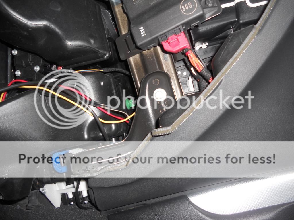
you are looking for the J519 module which is located in the drivers footwell right up at the top, a real PITA to get too

you need to remove the row of fuses but just unclipping the them and remove the piece of black air ducting by removing the T20 torx screw


Once you have located the J519 module you need to find the black plug (D) and the Grey connector


For the black connector you need to slide out the purple slider and push the pin into slot 14 which is marked on the plug itself, and the cover on the grey plug slides off and the pin goes into slot 17, again all numbered


find a suitable point for grounding both wires, any bolt should work, sorry forgot to take a pic of this
Once connected tidy all your wires and refit all trim pieces in reverse to how you took them off and plug all the lights in place
Now comes the programming:
09 control module, 07 long code helper, Byte 16 and tick Bits 0,1 and 6
then in
56 Radio module, 07 long code helper, Byte 8 and tick Bit 7
info from here:
post 70: Retrofit Footwell Lighting - Page 3 - A5_OC
And Enjoy:

Hope this helps people out
Thanks
John
This is my guide to retrofit footwell lights front and rear to a Audi A4 (B8 chassis)
This is the way I chose to install the lights and will accept no responsibility for any damage/ injuries caused by following this guide, others may have different ways to do this, so please use this as a guide only
Ok, so I ordered the kit from RobinA3, a member on here, which was made up following measurements I gave him as this is the first A4 her has made the kit for. The kit was made to a very high standard and arrived very quickly.
Tools I used were:
Flat head driver to prise fuse covers off
Torx T20 bit
8mm socket
Torx T50
Rigid cable to fish cables under carpet and behind centre console
Insulation Tape
The kit:

So this is how I chose to do the install:
I started by removing the drivers fuse panel cover

And removing the piece of trim below the steering wheel which was held on by 3x 8mm bolts

Once the bolts are removed the panel will just pull loose and then the OBD port will need to be unclipped to fully remove the panel

And then removed the glovebox by removing the passenger side fuse panel cover and there are 6x 8mm bolts in total holding in the glove box, 3 inside, 2 below and 1 behind the fuse cover


The glove box should now pull out and unplug the brown plug to completely remove

once these are removed you will see the route for the cables to run behind the centre console

I then remove the trims on the bottom of the door that run towards the centre of the car to run the cables to the drivers and passengers seats for the rear foot well lights


Next to make life a lot easier the front seat should be removed with the T50 torx bit but I couldn't for the life of me get these out so decided on a different way

Under the seat you will see this black cover, remove this

Then with a rigid bit of cable, I used a piece of twin and earth (im a spark ha ha) I fished this between where the bottom trim was removed and where the black cover was removed

You are aiming for this under the seats

and wired


Re fit the black cover and tidy your cables, I tied them to the existing cables under the seat
then fit the cables down the side of the car, following the existing cables to the passenger footwell where you need to tape these cables and the ones for the front passenger together and fish them the drivers footwell behind the centre console, again I used a piece of rigid cable


Repeat this process for the rear drivers side footwell light and you should have all your cables ready to connect into the J519 module in the drivers footwell
Ok so now the connections
you are looking for the J519 module which is located in the drivers footwell right up at the top, a real PITA to get too

you need to remove the row of fuses but just unclipping the them and remove the piece of black air ducting by removing the T20 torx screw


Once you have located the J519 module you need to find the black plug (D) and the Grey connector


For the black connector you need to slide out the purple slider and push the pin into slot 14 which is marked on the plug itself, and the cover on the grey plug slides off and the pin goes into slot 17, again all numbered


find a suitable point for grounding both wires, any bolt should work, sorry forgot to take a pic of this
Once connected tidy all your wires and refit all trim pieces in reverse to how you took them off and plug all the lights in place
Now comes the programming:
09 control module, 07 long code helper, Byte 16 and tick Bits 0,1 and 6
then in
56 Radio module, 07 long code helper, Byte 8 and tick Bit 7
info from here:
post 70: Retrofit Footwell Lighting - Page 3 - A5_OC
And Enjoy:

Hope this helps people out
Thanks
John


