

gupsterg
Registered User
Hi fellow members
 ...
...
Below is the parts... please ref linked thread at end for info on part no,etc...
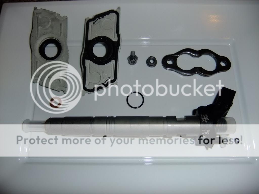
Besides the tools I already had I bought a Laser 4640 this is equiv. to the VAG tool & Laser 4984 these fitted perfectly on the HPFP & Inj.fuel in ports and a magnetic grab tool...
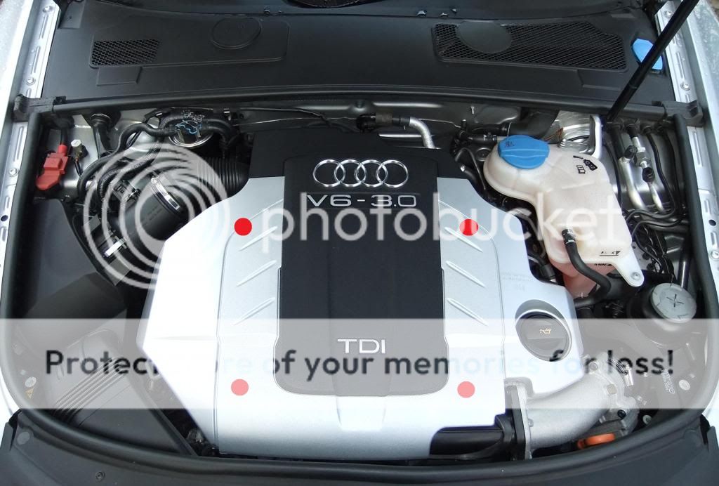
The engine cover is held on at points in red below, I would ease cover off as once I cracked one by being too heavy handed
 ...
...
I blasted the engine with compressed air before beginning work to remove any dirt/dust...
For Bank 1 remove air intake to turbo, air mass meter, the outer air box housing & duct to front grill... on refit I cleaned air filter housing and vacuum'd the air filter on the outside face, it was not that dirty as only done under a year ago...
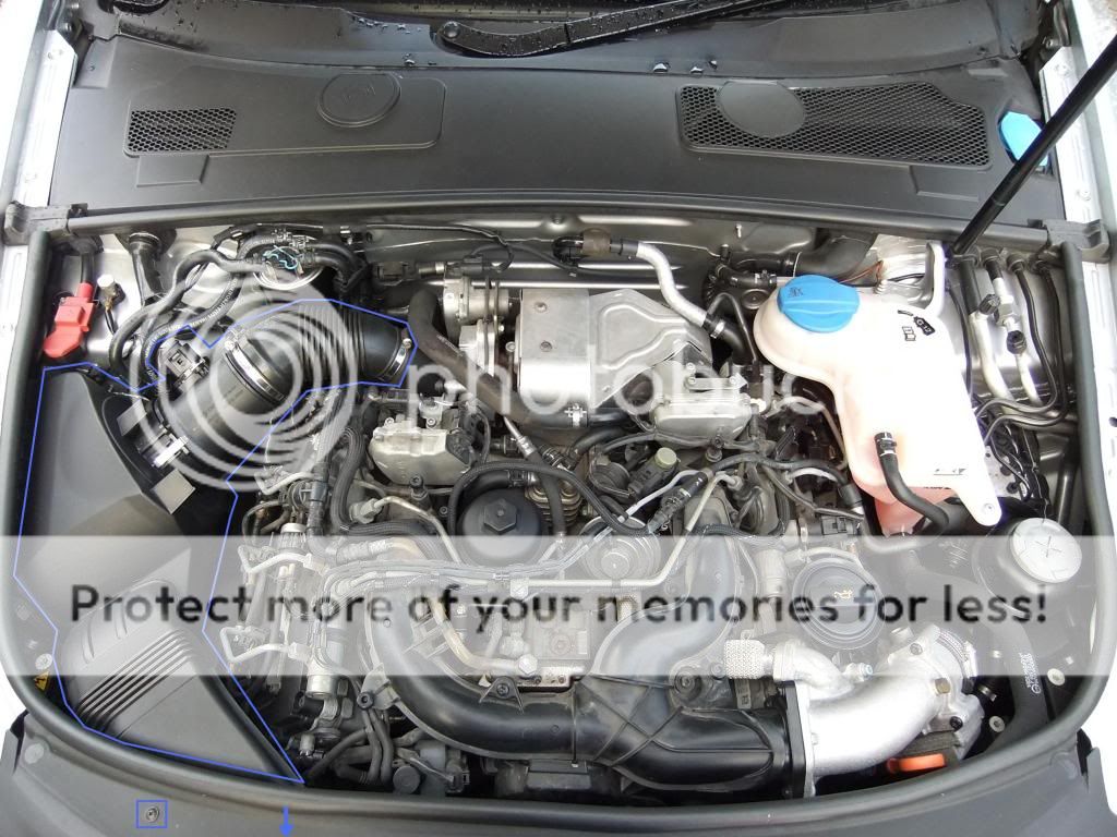
I closed port on turbo with bag and rubber band...

Next I removed the parts highlighted... the fuel return connections are released by placing fingertips on tabs and pulling round heads up... on refit I lubricate the fuel return "O"rings on injectors with diesel...
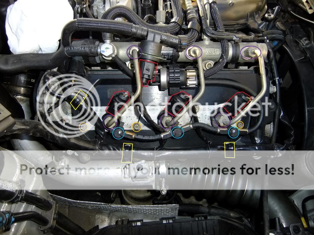
All HPFP were marked to fit back in the same place, they are all the same but on refit I wanted to place them all back in original positions...
I prep'd injectors before hand so could minimise engine open time... I used clean engine oil to lubricate the the "O" ring & inj.shaft, end cap fitting was also easier by doing this...

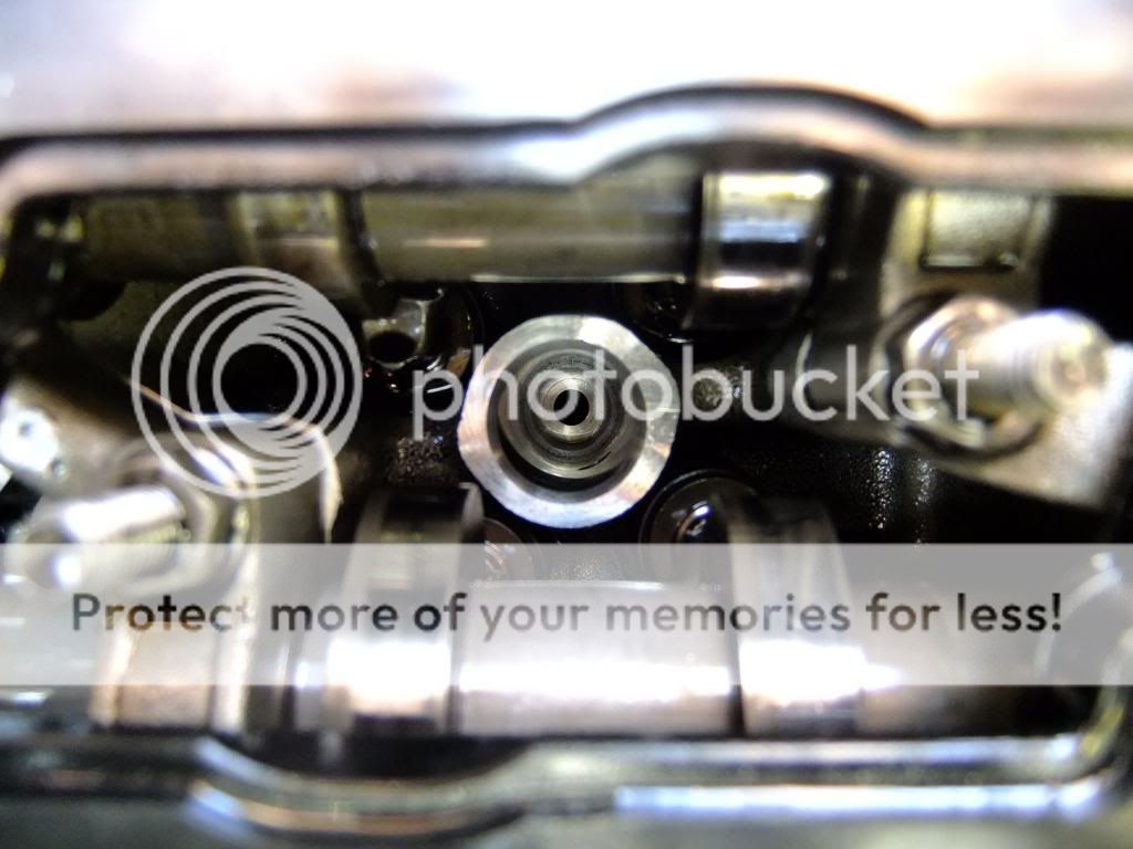
The view of Bank 1 Inj.Bore 1

The view of Bank 1 Inj.Bore 1 (mid clean)
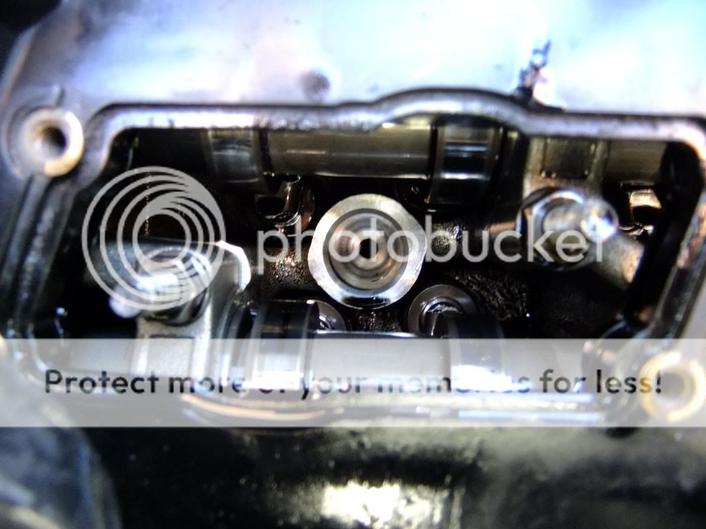
The view of Bank 1 Inj.Bore 2

The view of Bank 1 Inj.Bore 3

The view of Bank 1 Inj.Bore 3 (mid clean)
I first used my homemade vacuum tool (6mm PVC air line) to vacuum carbon form the inj.bores...

Then I used clean engine oil with my homemade tool (elec. wiring feed tool with cotton bud, apply tape with clean hands!) , this allowed clear view of the injector seat...

For Bank 2 coolant tank moved... I also removed the screws to the throttle body later to allow better access to Inj.4 on bank 2...
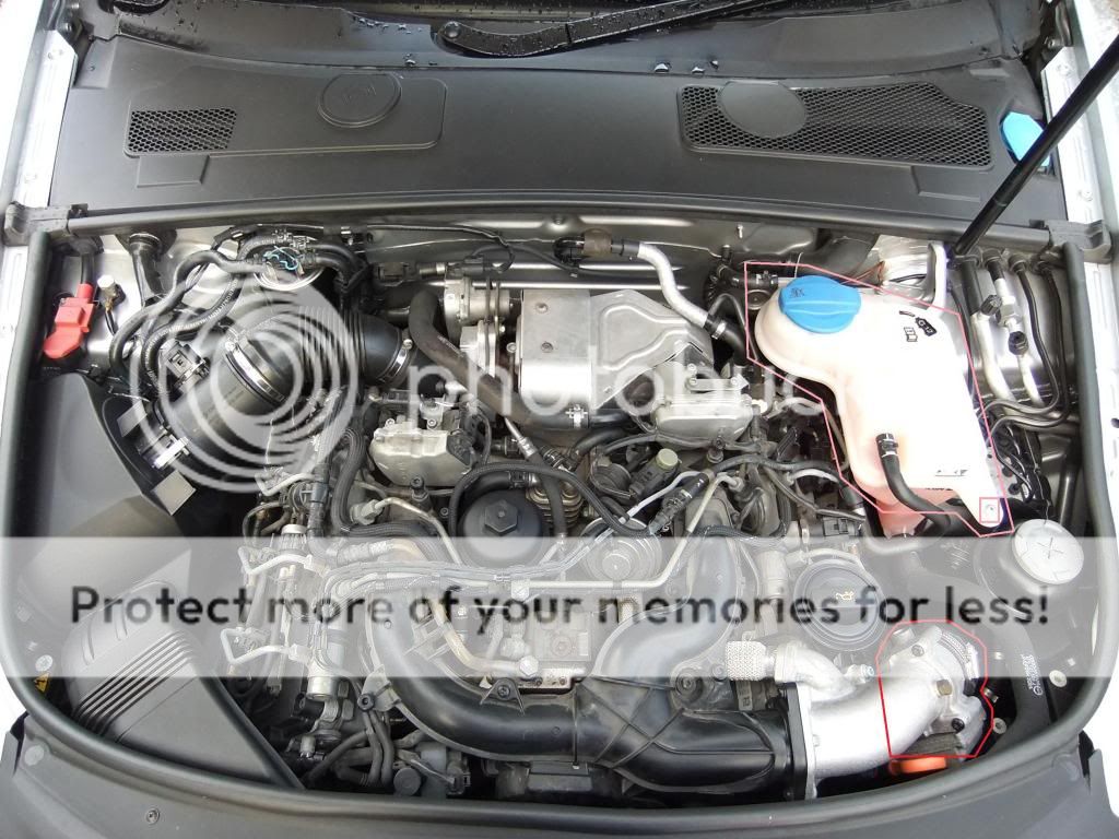

I removed some coolant with large syringe, clamped the hoses, unplugged lower elec.connection to coolant level sender...
I also had to remove the screw for the wiring harness on bank 2...

The trickiest part as I did not have magnetic sockets was Inj.4 clamp nut close to oil filler neck... the magnetic grab tool came handy here...
I had thought about using grease in socket but did not wish to contaminate the oil/internals...
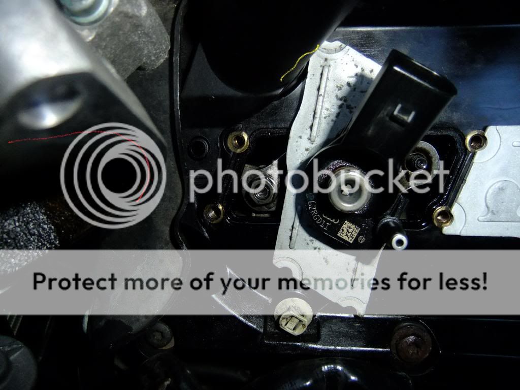
I also had to clean off some corrosion on the HPFP...

I just used diesel and light rubbing action with fingertips, on refit I lubricated the threads of the relevant connections with diesel, first locating the pipes & viewing their mating points and then hand tightening the flare nuts...
I also noted some cracks in fuel return pipes...
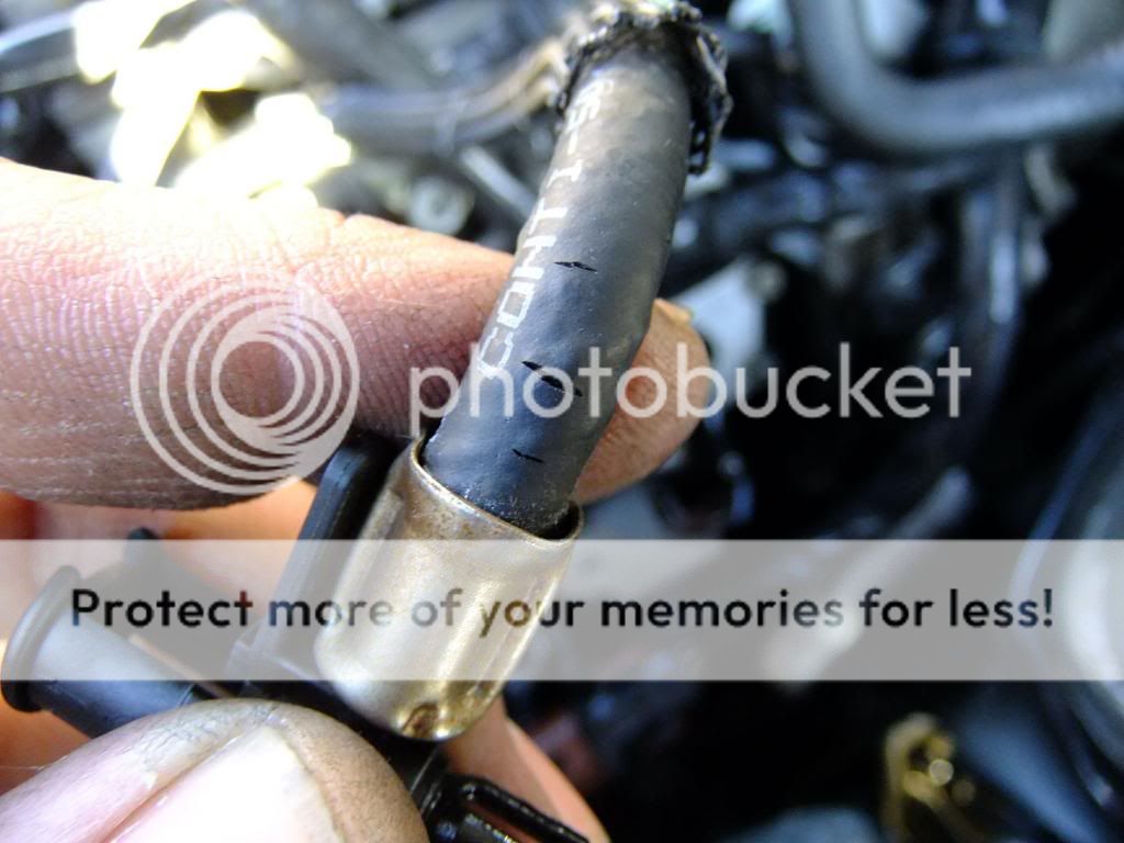
Above was the section under the coolant tank... if I'd know before hand would have tried to have solution/parts to hand... as not leaking fuel have left for the time being...
For tightening torques ref Link:- Fuel system exploded view
Coding was done before startup of engine via VCDS... the new injector calibration codes will be on the collar at the inj.fuel in port...
[Select]
[01 - Engine]
[Adaptation - 10]
Channel 071: IMA-ISA Value for Cylinder 1
Channel 072: IMA-ISA Value for Cylinder 2
Channel 073: IMA-ISA Value for Cylinder 3
Channel 074: IMA-ISA Value for Cylinder 4
Channel 075: IMA-ISA Value for Cylinder 5
Channel 076: IMA-ISA Value for Cylinder 6
[Test]
[Save]
[Done, Go Back]
Switch Ignition OFF, wait 10 seconds and switch Ignition ON again. The values should be saved now, please verify them by double checking the adaptation values.
I also done this...
[Select]
[01 - Engine
[Basic Settings - 04]
Set Group to "035"
[Go!]
[ON/OFF/Next]
The electric fuel pump should run for 30 seconds
If the vehicle had a simple repair such as a fuel filter that should be a sufficient amount of time for the filter to fill up.
If the engine had extensive repairs such as injector replacement and/or fuel system flushing this process should be repeated no less than 3 times. Click [On/Off/Next] to reinitialize the process if needed.
[Done, Go Back]
I couldn't verify at the time if this function on my engine but did it anyway...
Engine may not start first time and cut out with a low oil pressure warning... initiate startup again... fuel system will self bleed...
Let engine idle for 5-10mins do not rev engine...
Here is a log of the adaptation of injectors after change over Link:- View attachment Log-injectors final.txt
I think I covered all I did but will update if recall anything more
 ...
...
Please read in full, take things slowly when doing especially when removing the nuts on injector clamp as if they fall they will be in the camshafts/valve train, I found cleaning the oil of them helped also, have the magnetic tool to hand, I also used a tweezer to lift/grab them off last threads...
Thanks to the VWAF team for help with this
 ...
...
A8 Tech, Crasher & of course my many supportive VWAF friends, especially SPARKER and SNAPDRAGON for his first hand tips
...
Ref link:- A6/C6 injector PROBLEM - Replacement/refurbished injectors possible?
This is an experience share for others to use as they wish!
Below is the parts... please ref linked thread at end for info on part no,etc...
Besides the tools I already had I bought a Laser 4640 this is equiv. to the VAG tool & Laser 4984 these fitted perfectly on the HPFP & Inj.fuel in ports and a magnetic grab tool...
The engine cover is held on at points in red below, I would ease cover off as once I cracked one by being too heavy handed
I blasted the engine with compressed air before beginning work to remove any dirt/dust...
For Bank 1 remove air intake to turbo, air mass meter, the outer air box housing & duct to front grill... on refit I cleaned air filter housing and vacuum'd the air filter on the outside face, it was not that dirty as only done under a year ago...
I closed port on turbo with bag and rubber band...
Next I removed the parts highlighted... the fuel return connections are released by placing fingertips on tabs and pulling round heads up... on refit I lubricate the fuel return "O"rings on injectors with diesel...
All HPFP were marked to fit back in the same place, they are all the same but on refit I wanted to place them all back in original positions...
I prep'd injectors before hand so could minimise engine open time... I used clean engine oil to lubricate the the "O" ring & inj.shaft, end cap fitting was also easier by doing this...
The view of Bank 1 Inj.Bore 1
The view of Bank 1 Inj.Bore 1 (mid clean)
The view of Bank 1 Inj.Bore 2
The view of Bank 1 Inj.Bore 3
The view of Bank 1 Inj.Bore 3 (mid clean)
I first used my homemade vacuum tool (6mm PVC air line) to vacuum carbon form the inj.bores...
Then I used clean engine oil with my homemade tool (elec. wiring feed tool with cotton bud, apply tape with clean hands!) , this allowed clear view of the injector seat...
For Bank 2 coolant tank moved... I also removed the screws to the throttle body later to allow better access to Inj.4 on bank 2...
I removed some coolant with large syringe, clamped the hoses, unplugged lower elec.connection to coolant level sender...
I also had to remove the screw for the wiring harness on bank 2...
The trickiest part as I did not have magnetic sockets was Inj.4 clamp nut close to oil filler neck... the magnetic grab tool came handy here...
I had thought about using grease in socket but did not wish to contaminate the oil/internals...
I also had to clean off some corrosion on the HPFP...
I just used diesel and light rubbing action with fingertips, on refit I lubricated the threads of the relevant connections with diesel, first locating the pipes & viewing their mating points and then hand tightening the flare nuts...
I also noted some cracks in fuel return pipes...
Above was the section under the coolant tank... if I'd know before hand would have tried to have solution/parts to hand... as not leaking fuel have left for the time being...
For tightening torques ref Link:- Fuel system exploded view
Coding was done before startup of engine via VCDS... the new injector calibration codes will be on the collar at the inj.fuel in port...
[Select]
[01 - Engine]
[Adaptation - 10]
Channel 071: IMA-ISA Value for Cylinder 1
Channel 072: IMA-ISA Value for Cylinder 2
Channel 073: IMA-ISA Value for Cylinder 3
Channel 074: IMA-ISA Value for Cylinder 4
Channel 075: IMA-ISA Value for Cylinder 5
Channel 076: IMA-ISA Value for Cylinder 6
[Test]
[Save]
[Done, Go Back]
Switch Ignition OFF, wait 10 seconds and switch Ignition ON again. The values should be saved now, please verify them by double checking the adaptation values.
I also done this...
[Select]
[01 - Engine
[Basic Settings - 04]
Set Group to "035"
[Go!]
[ON/OFF/Next]
The electric fuel pump should run for 30 seconds
If the vehicle had a simple repair such as a fuel filter that should be a sufficient amount of time for the filter to fill up.
If the engine had extensive repairs such as injector replacement and/or fuel system flushing this process should be repeated no less than 3 times. Click [On/Off/Next] to reinitialize the process if needed.
[Done, Go Back]
I couldn't verify at the time if this function on my engine but did it anyway...
Engine may not start first time and cut out with a low oil pressure warning... initiate startup again... fuel system will self bleed...
Let engine idle for 5-10mins do not rev engine...
Here is a log of the adaptation of injectors after change over Link:- View attachment Log-injectors final.txt
I think I covered all I did but will update if recall anything more
Please read in full, take things slowly when doing especially when removing the nuts on injector clamp as if they fall they will be in the camshafts/valve train, I found cleaning the oil of them helped also, have the magnetic tool to hand, I also used a tweezer to lift/grab them off last threads...
Thanks to the VWAF team for help with this
A8 Tech, Crasher & of course my many supportive VWAF friends, especially SPARKER and SNAPDRAGON for his first hand tips
Ref link:- A6/C6 injector PROBLEM - Replacement/refurbished injectors possible?
This is an experience share for others to use as they wish!
