Facelift Clocks in Pre-Facelift

ScottD3

I want your faulty electronics
Supporter
Joined
Nov 24, 2010
Messages
15,084
Reaction score
1,131
Points
113
Location
Plymouth
Website
wheelsnwires.blogspot.com
Almost two years ago I started this thread http://www.audi-sport.net/vb/a4-s4-forum-b5-chassis/134267-small-project.html but its full of my questions and some random ramblings by myself.
So I thought its about time I cleaned it up and made an attempt to document it properly.


The difference between PFL (Prefacelift) and FL (Facelift) clocks are not massive but its enough to want me to change.

On the Face:
FL clocks have a digital clock with date. PFL have a analogue clock.
FL clocks have white dial numbers. PFL are all read.
FL clocks are able to display which door, boot or bonnet is open. PFL can't.
FL clocks will display satnav directions. PFL can't

On the back. Mainly the plug:
FL clocks use a blue, green and grey plug all with 32 pins. PFL clocks use a Red, green and blue plug.
FL clocks have the option to use a radio controls clock. PFL clocks don't.

Communication/function:
FL clocks has can bus and uses it. PFL clocks don't.
FL clocks lights will turn on when the lights are on. PFL clock lights are on all the time.
FL clocks has a oil level warning. PFL clocks don't.

I think that's the basic changed between the two.


To fit FL clocks in your car you need several tools, some from off the top of my head are as follow:
Torx screw driver to remove the clocks.
VCDS and Vag tacho/commander type software or a friendly lock smith bloke who can program keys, match your miles and do a bit of coding later on.
a selection of spanners, sockets and such to remove the sump.
Soldering iron, wire strippers, cables and other such electrical wiring items.

With tools together you need to get your parts.

First you need your FL clocks.


A sump that will fit your car with the oil level sensor hole.


A level sensor with plug
IMAG0712.jpg


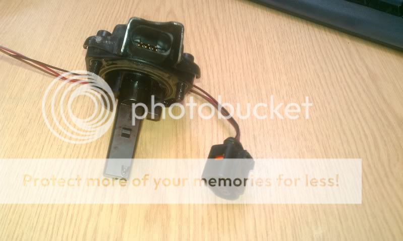
Depending on how you want to wire your FL clocks in your car your got two options.
You can either go and head and wire the new grey plug in and reroute all cables straight away or make an adaptor loom like I used.


Personally I recommend going down the adaptor loom route. it will take a bit more time cause you got to make it but its great for testing and if needed you can unplug the new clocks and plug your original ones in with out the car being immobile plug you get a better understanding of the wiring changes that will be needed.
This route is also a pain cause you got to get a set of PFL clocks and strip the plugs out.

Like this:


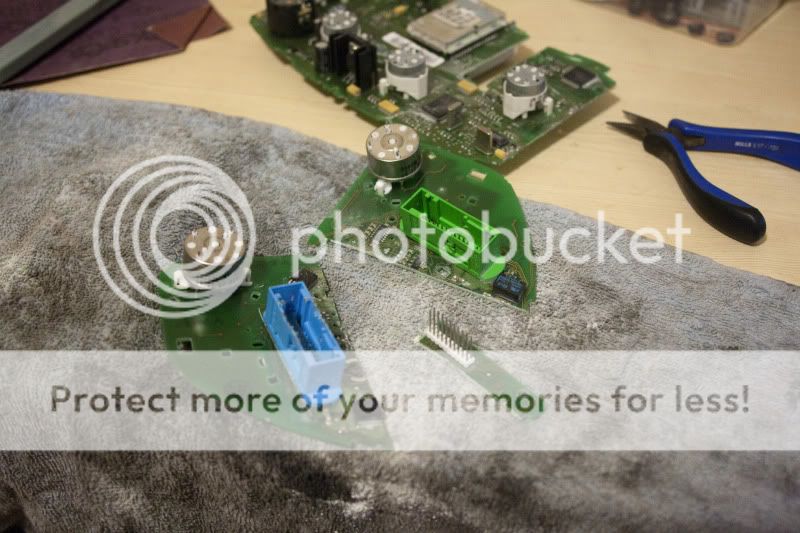
What ever route you take you will need to match the wirings up from PFL cluster to FL cluster.
 
  • Like
Reactions: olds_kool
Pin assignment at multi-pin connectors on instrument cluster - vehicles from model year 1998
Multi-pin connector, 32-pin, blue
1 -Terminal 15
2 -Turn signal (right-side)
3 -Speedometer output 1
4 -Not used
5 -Fuel gauge sender
6 -Airbag
7 -Terminal 31 (sensor earth)
8 -Coolant temperature
9 -Terminal 31 (load earth)
10 -Oil pressure switch
11 -Engine speed signal
12 -Terminal 61
13 -Glow period warning lamp or CAT
14 -Self-levelling suspension
15 -Terminal 58d
16 -Trailer turn signal / fault in engine electrical system
17 -Main beams
18 -Turn signal (left-side)
19 -ABS
20 -Terminal 58s
21 -Door contact, driver's side
22 -Coolant level low
23 -Terminal 30
24 -Terminal 31 (load earth)
25 -K wire
26 -Right parking light
27 -Left parking light
28 -Speedometer input
29 -Brake fluid level/pressure
30 -S contact
31 -Belt buckle
32 -ESP
A90-0076.png
Multi-pin connector, 32-pin, green
1 -Not used
2 -Transponder 1
3 -Not used
4 -Immobilizer
5 -W wire
6 -Boot lid/tailgate (Lowline version only)
7 -Brake pads (Highline version only)
8 -Not used
9 -Not used
10 -Fuel tank warning output signal for engine control unit (only on 6-cylinder TDI and on export versions for USA)
11 -Standing time output
12 -Air conditioner shut-off
13 -Handbrake
14 -Electronic throttle
15 -Parking lights
16 -Not used
17 -Transponder 2
18 -Not used
19 -Not used
20 -Not used
21 -Oil temperature
22 -Not used
23 -Not used
24 -Not used
25 -Not used
26 -Not used
27 -Not used
28 -Not used
29 -Terminal 58d (external dimmer potentiometer)
30 -Speedometer output 2
31 -Not used
32 -Not used
A90-0077.png
Multi-pin connector, 20-pin, red
1 -Fuel consumption signal
2 -Not used
3 -Not used
4 -Not used
5 -Ambient temperature
6 -Selector lever position indicator
7 -Not used
8 -Not used
9 -Washer fluid low
10 -Hydraulic pressure
11 -On-board computer reset
12 -Clock signal for radio frequency display
13 -Data signal for radio frequency display
14 -On-board computer, left
15 -Enable signal for radio frequency display
16 -Tail lights / dipped beams (bulb monitor)
17 -Glow plug relay (on TDI engines the low-voltage monitor in the instrument cluster is disabled while the glow plugs are activated)
18 -On-board computer, right
19 -Brake light
20 -Not used
 
Pin assignment at multi-pin connectors on instrument cluster (2000my)
Multi-pin connector, 32-pin, blue
1 -Terminal 15
2 -Brake pad wear
3 -Speedometer (output 1)
4 -Not used
5 -Fuel gauge sender
6 -Fuel tank warning OBD 2
7 -Terminal 31 (sensor earth)
8 -Coolant temperature
9 -Terminal 31 (load earth)
10 -Oil pressure 2 (high)
11 -Engine speed signal
12 -Air conditioner shut-off
13 -Electronic throttle / glow period warning lamp
14 -Self-levelling suspension
15 -Terminal 58d
16 -Turn signal (trailer)
17 -Main beams
18 -Turn signal (left-side)
19 -Not used
20 -Terminal 58s
21 -Driver's door contact
22 -Coolant level low
23 -Terminal 30
24 -Terminal 31 (load earth)
25 -Fuel consumption signal
26 -Right parking light
27 -Left parking light
28 -Speedometer input
29 -Brake
30 -S contact
31 -Speedometer (output 2)
32 -ESP/ASR (TCS)
A90-0132.png
Multi-pin connector, 32-pin, green
1 -Door contact (all doors)
2 -Transponder 1
3 -Not used
4 -Not used
5 -W wire
6 -Rear lid
7 -Turn signal (right-side)
8 -Not used
9 -Not used
10 -Airbag
11 -Standing time output
12 -Terminal 61/charge warning
13 -Parking brake / BRAKE
14 -CHECK
15 -Oil level / oil temperature
16 -Not used
17 -Transponder 2
18 -CAN high speed, power train (+)
19 -CAN high speed, power train (–)
20 -CAN high speed, power train (screening)
21 -ABS
22 -CAN low speed, convenience (+)
23 -CAN low speed, convenience (–)
24 -CAN low speed, convenience (screening)
25 -Bonnet
26 -Not used
27 -Belt buckle
28 -K wire
29 -Ambient temperature input
30 -Not used
31 -Selector lever display
32 -Not used
A90-0131.png
Multi-pin connector, 32-pin, grey
1 -Menu switch (menu)
2 -Menu switch (out A)
3 -Menu switch (out B)
4 -Menu switch (enter)
5 -CAN high speed, display (+)
6 -CAN high speed, display (–)
7 -CAN high speed, display (screening)
8 -Passenger's door contact
9 -Door contact, rear right
10 -Door contact, rear left
11 -Enable
12 -Clock
13 -Data
14 -Brake light
15 -Washer fluid level
16 -Tail lights / dipped beams
17 -On-board computer, left
18 -On-board computer, right
19 -On-board computer reset
20 -Not used
21 -Not used
22 -Not used
23 -Control group 1, Navigation system
24 -Control group 2, Navigation system
25 -Control group, Telematics
26 -Not used
27 -Not used
28 -Not used
29 -Not used
30 -Not used
31 -Not used
32 -Not used
A90-0133.png
Multi-pin connector, 4-pin, black, for radio-controlled clock
1 -Radio-controlled clock signal (data)
2 -Radio-controlled clock 5V
3 -Not used
4 -Radio-controlled clock earth
 
Once you've sat down and sort your loom out or made the adaptor you also need to the fit the sump with oil level sensor and route that back to where the clocks are.
Its just 3 cables, power, earth and signal.

With all that done, its time to sit down and do some programming to get your keys working and your rev counter.


First off you need the SKC code for your new clocks. You can do this if you or a mate has VAG tacho or VAG commander.

When you got the SKC you can follow these instructions.
[h=2]Key Matching[/h]Prerequisites:

  • While adapting each key, make sure to place the other keys away from the ignition lock (reader coil). The passenger seat is an adequate place.
  • You must have all of the keys you intend to be able to use, including the valet key if you have one.
  • Battery voltage at least 12.5 V.

[Select]
[17 - Instruments]
[Login - 11]

  • 4-digit PIN
    • Enter zero followed by the 4-digit PIN. For example, if your PIN is 1234, enter 01234.
    • [Do It!]

[Adaptation - 10]
Enter 21 in "Channel Number".
[Read]
The "Stored Value" is the number of keys currently matched.
Enter a "new value" corresponding to the total number of keys to be matched, including any existing keys.
Any old keys are automatically being cleared. All keys, including existing keys, must be matched at the same time.
[Save]
[Done, Go Back]
[Close Controller, Go Back - 06]

  • Repeat the following steps until all Keys have been matched:
    • Switch Ignition OFF and remove Key.
    • Insert the next Key and switch Ignition ON.
    • The Immobilizer Warning Light will light up for ~2 seconds, wait until it goes out, indicating that the key has been matched.
Note: The above steps must be completed within 60 seconds after saving the Adaptation!

That should get your key coded to your cluster and if everything else is plugged in and working, it should start and run the car but you will get errors about oil pressure cause your rev counter is not working.
That's next.

with VCDS out and still connected, go back to the clocks, go to adaptation, channel 60.
Channel 60 should be Can-bus power train, I think this label depends on what version of VCDS you are using.
Hopefully when the little help box pops up you should see something like this.

IMG-20130903-WA0009_zps0c744275.jpg


My cluster was set to 01025 but by changing it to 0 it got the revs working.
Hopefully this will be the same for everyone else.

You will have some cables left over and the odd cable that has no where to go in the PFL loom and visa-versa.
I've not noticed any thing not working due to these cable.

The only cables that will have no where to go that you might want are the door, boot and bonnet signal cables.
These are basic earth cables, you earth them and it thinks that door is open.
I've not wired these up yet but I will be wiring them in to the pin switches to get them to work.

You will have a disc cable left over, that one can just be earthed and ignored, unless you want to wire that up but I don't think its needed.

I also think this is the same process for the A3 8Ls but hopefully I will find out next year and report back.

That's pretty much it.
I'm not sure what else is needed?
 
You are officially the world expert on this Scott.