

I decided to retrofit my A4 B5 ".5TDi Quattro with cruise control, as the wife's already had and I felt left out.
I bought the Kufatech loom KUFATEC GmbH & Co. KG - Kabelsatz GRA Audi A4 B5 30096, for £18 plus delivery and VAT, coming to £27 all in. I had to wait whilst they made the loom up. I got the stalk from All Audi, for about £25.
Once all my parts arrived, I started work.
First I DISCONNECTED THE BATTERY - there is work on the fusebox - then I removed the steering wheel, stalks,and dashboard for access, There is plenty of info around on how to do this, so I wont lay it out here.
Next, under the bonnet, I accessed and removed the engine ECU.
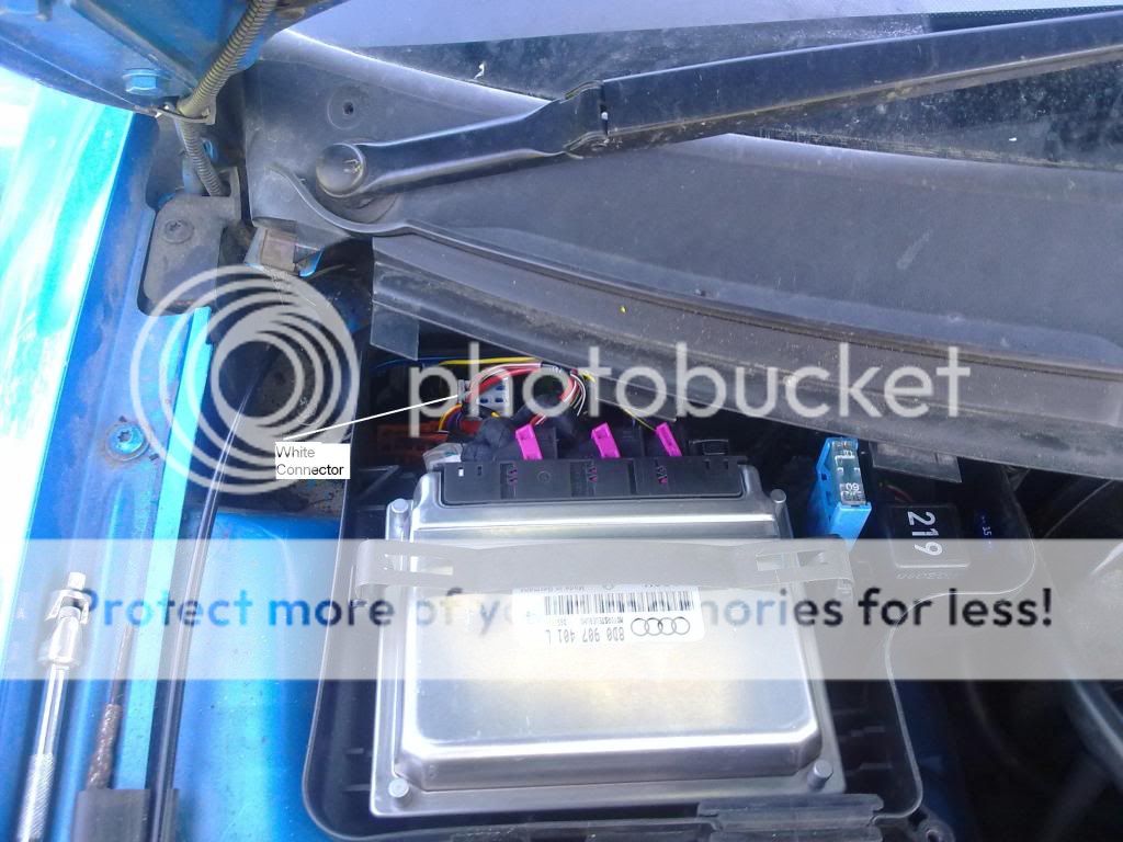
Notice I did not have to remove the Scuttle around the wipers - I removed the screws with a 1/4" ratchet and 8mm socket. It was a little fiddly, but not hard. This accessed the 'White Connector' mentioned in all the help guides.
I then removed the ECU and the ECU box, for access
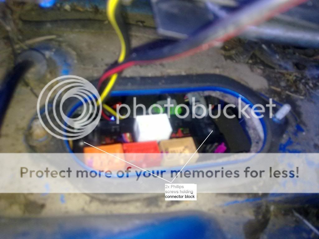
I then removed the 2 screws to release the connector block.
Next, I fed the loom and block of connectors through the footwell so I could release the connector, the picture shows the release tags

and the view from the footwell

I then fed the loom down through the column and footwell
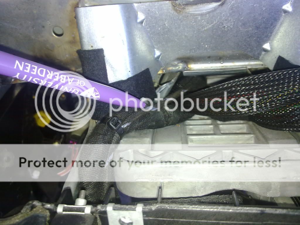
leaving it unsecured at the moment (unlike the picture), so I could fit the pins
The connector is in two parts, and only on side is needed. The two parts are locked together with a clip.
Then the pins are accessed by sliding out the top part of the connector, agian secured with a clip. The pictures show the pin numbers, as the connectors are not marked.
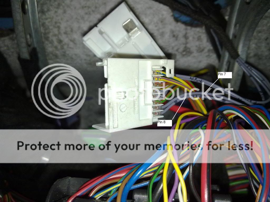
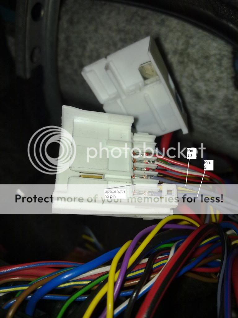
For those who are interested, for orientation, the pin numbers/colours are as follows: Pin 6 is Brown and Green
Pin 7 is Red and Green
Pin 8 is Blue
Pin 9 is Red and Yellow
There is a blank space with no pin
Pin 10 is Black and White
Pin 11 is Black and Red
The loom has pin numbers printed along it, with the power wire being seperate., from the main ECU loom The pins just push into the connector. Make sure they are the right way around first, as I did not have to remove any, so I don't know how they lock in.
Refit the connector lock, and clip the two halves together
,

put it back in the block and refit the block and the rest of the ECU parts.
I then removed the fusebox for access, and fed the power supply wire into it, an spliced it into the wire off Fuse 31, which the owners manual lists as the Cruise Control fuse.

Note I used a proper environmental splice (bought from Maplins HeatShrinkable Cable Splicers : Crimp Terminals : Maplin ), not a crappy Halfords red butt splice, nor did I solder it. This will guard against future connection problems.
I then secured the loom with tyraps alomg the existing looms

Then it was a case of refit dash, fit the stalks back onto the column
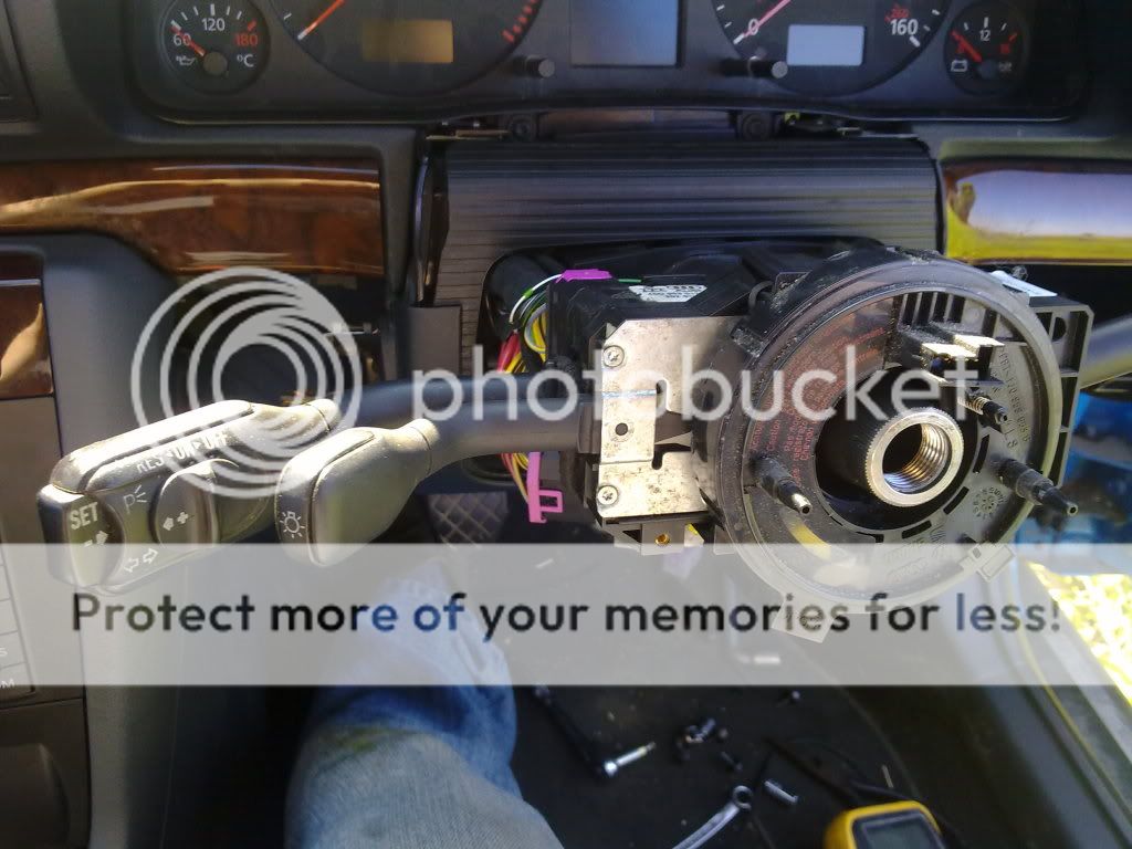
and refit the wheel.
The next step is to encode the ECU via VCDS, Select 01 Engine
Select 11 Login
Login code is 11463 to activate
Robert is your fathers brother.
If you want to test it via VCDS,Select 01 Engine
Select 08 Measuring Blocks
Zone 4 should NOT read 255 (CC deactivated)
Zone 3 bits should all be '0' with CC off. On, Set, Resume, Brake on and Clutch on all show as bit '1'
Finally, a road test is always good, the owners manual gives the funtions available.
I bought the Kufatech loom KUFATEC GmbH & Co. KG - Kabelsatz GRA Audi A4 B5 30096, for £18 plus delivery and VAT, coming to £27 all in. I had to wait whilst they made the loom up. I got the stalk from All Audi, for about £25.
Once all my parts arrived, I started work.
First I DISCONNECTED THE BATTERY - there is work on the fusebox - then I removed the steering wheel, stalks,and dashboard for access, There is plenty of info around on how to do this, so I wont lay it out here.
Next, under the bonnet, I accessed and removed the engine ECU.
Notice I did not have to remove the Scuttle around the wipers - I removed the screws with a 1/4" ratchet and 8mm socket. It was a little fiddly, but not hard. This accessed the 'White Connector' mentioned in all the help guides.
I then removed the ECU and the ECU box, for access
I then removed the 2 screws to release the connector block.
Next, I fed the loom and block of connectors through the footwell so I could release the connector, the picture shows the release tags
and the view from the footwell
I then fed the loom down through the column and footwell
leaving it unsecured at the moment (unlike the picture), so I could fit the pins
The connector is in two parts, and only on side is needed. The two parts are locked together with a clip.
Then the pins are accessed by sliding out the top part of the connector, agian secured with a clip. The pictures show the pin numbers, as the connectors are not marked.
For those who are interested, for orientation, the pin numbers/colours are as follows: Pin 6 is Brown and Green
Pin 7 is Red and Green
Pin 8 is Blue
Pin 9 is Red and Yellow
There is a blank space with no pin
Pin 10 is Black and White
Pin 11 is Black and Red
The loom has pin numbers printed along it, with the power wire being seperate., from the main ECU loom The pins just push into the connector. Make sure they are the right way around first, as I did not have to remove any, so I don't know how they lock in.
Refit the connector lock, and clip the two halves together
,
put it back in the block and refit the block and the rest of the ECU parts.
I then removed the fusebox for access, and fed the power supply wire into it, an spliced it into the wire off Fuse 31, which the owners manual lists as the Cruise Control fuse.
Note I used a proper environmental splice (bought from Maplins HeatShrinkable Cable Splicers : Crimp Terminals : Maplin ), not a crappy Halfords red butt splice, nor did I solder it. This will guard against future connection problems.
I then secured the loom with tyraps alomg the existing looms
Then it was a case of refit dash, fit the stalks back onto the column
and refit the wheel.
The next step is to encode the ECU via VCDS, Select 01 Engine
Select 11 Login
Login code is 11463 to activate
Robert is your fathers brother.
If you want to test it via VCDS,Select 01 Engine
Select 08 Measuring Blocks
Zone 4 should NOT read 255 (CC deactivated)
Zone 3 bits should all be '0' with CC off. On, Set, Resume, Brake on and Clutch on all show as bit '1'
Finally, a road test is always good, the owners manual gives the funtions available.


