I just though I would write a quick how-to guide for fitting flush parking sensors, as I don't think there is one for this particular type.
My car is an A4 b6 1.9tdi sport saloon.
I purchased this kit - the cobra park master 0358
This kit comes with fitting instructions but only pictures so I thought it may help someone else out in the future.
Tools needed : drill, torx set, socket set screwdrivers (flat and Phillips), 2mm drill bit, 17mm hole saw, tape, scissors, small tie wraps, fine marker pen, staley knife, wire snips/stripper, wire tester and lots of patience!")
First steps first, once receiving the sensors they need to be painted to gain the best results.
I'm quite handy with paint so I sprayed them myself with aerosol cans (colour matched to my car) I applied 2 thin coats of plastic primer, and two thin coats of colour.
Caution - when spraying the sensors keep the coats thin and keep the sensors in the holder provided.
Once they have been left to dry for 24 hrs. You can then begin to get the car ready for installation.
Step 1 - open your boot, and remove your boot floor carpet, spare wheel and all the rubbish in your boot!
You then need remove the side panels from inside the boot, I think this is different from saloon to avant but I'm not 100% sure,
Step 2 - Remove the 4 luggage hooks from the boot floor using a torx key or bit and remove from the car.

Step 3 - unclip the boot side panels, they are on clips all the way around so give the a steady pull all the way around.
Once they have been removed its time to remove the rear lights and bumper.
Step 4 - remove the rear lights with a 8mm socket or Phillips screw driver. There is only one bolt holding them in and two ball and socket clips. Unclip the electrical plug connection
Step 5 - Remove the boot rear plastic panel housing the boot light. It is held in by one 10mm nut.
Once the inner panel has been removed the next step is to remove the bumper.
There are six nuts and 3 plugs at each side holding the rear bumper as well as 2 screws underneath the rear bumper.


Step 6 - remove the underneath screws first using a torx bit. The remove all of the 12 internal screws.
Step 7 - once they have all been remove the bumper then needs to be removed
Caution - the 6 clips attached can be very tough so I would advise some one to assist in pushing them from the inside as you pull from the outside.
Once the bumper is removed, lay it face down onto something that will prevent it getting scratched.

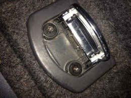
Step 8 - locate the 4 crosses ( look like targets) on the rear of the bumper - this is where the location of the factory fit sensors are situated. See image;

Step 9 - using the 2mm drill bit drill from the rear of the bumper in the centre of the target.


Step 10 - from the front of the bumper, drill using the 17mm hole saw, remove burrs with fingers.
Caution - cover the paintwork with masking tape over the paint, go steady as you don't want to damage the paintwork.


Step 11 - peel one side of the sticky pad and stick it onto the mount as per photo.


Step 12 - screw the sensors into the mounting holders as per instructions,

Step 13 - offer up the sensor to the rear of the bumper, to check the screw distance is ok. - this step is more obvious when you have the sensor in hand. This is to make sure the sensor is flush with the bumper face and not protruding.

Step 14 - once you are happy with the sensor positions in the holes, making sure you have them numbers in the correct orientation, leave them in that position.
Step 15 - clean around the holes on the bumper, and dry. A clean dry surface is essential.
Caution - latex gloves should be worn at this point!
Step 16 - apply the adhesive promoter around the hole, with the sponge pad provided


Step 17 - this step is to stick the sensors to the bumper, the plug on the rear of the sensor should point downwards to prevent any water ingress in the plug/ electrics.
Remove the red side of the sticky pad, line up the sensor in the hole, and stick the sensor in the hole, applying pressure around the pad for around 5 seconds.
Step 18 - Once all the sensors are in, you need to wire them up with the corresponding numbers. Trace all the wires to the passenger side of the car where you will find a rubber plug/ bung. Stick with tape or tie wrap to the rear of the bumper
Caution - check that the wires do not pass on any tight points when the bumper is re-fitted.
Step 19 - Remove the bung and cut/ drill a hole in the centre. Pass all the wires through the hold in the bung.

Step 20 - stick the control unit on the wall of the car behind the boot side wall. And clip the wires into the correct holes - they are numbered.

Step 21 - stick the buzzer in the boot where you think is best to be heard around the car. I placed mine under the sub grill on the roof of the boot, and traced the wire to the passenger side and dropped it down through one of the holes.


Step 22 - Clip the buzzer plug in the control unit and earth the unit with one of the bolts in the area.
Step 23 - tap into the reverse light wire to allow power to the unit when the reverse gear is engaged.
I good old Haynes style, rift it the bumper lights and boot sides reverse of removal.
Here awesome pictures of the completed look of the sensors, is is a fantastic piece of kit!!


Not sure why the last image is the wrong way!
I hope this helps someone.
HARRIBO66
My car is an A4 b6 1.9tdi sport saloon.
I purchased this kit - the cobra park master 0358
This kit comes with fitting instructions but only pictures so I thought it may help someone else out in the future.
Tools needed : drill, torx set, socket set screwdrivers (flat and Phillips), 2mm drill bit, 17mm hole saw, tape, scissors, small tie wraps, fine marker pen, staley knife, wire snips/stripper, wire tester and lots of patience!
First steps first, once receiving the sensors they need to be painted to gain the best results.
I'm quite handy with paint so I sprayed them myself with aerosol cans (colour matched to my car) I applied 2 thin coats of plastic primer, and two thin coats of colour.
Caution - when spraying the sensors keep the coats thin and keep the sensors in the holder provided.
Once they have been left to dry for 24 hrs. You can then begin to get the car ready for installation.
Step 1 - open your boot, and remove your boot floor carpet, spare wheel and all the rubbish in your boot!
You then need remove the side panels from inside the boot, I think this is different from saloon to avant but I'm not 100% sure,
Step 2 - Remove the 4 luggage hooks from the boot floor using a torx key or bit and remove from the car.
Step 3 - unclip the boot side panels, they are on clips all the way around so give the a steady pull all the way around.
Once they have been removed its time to remove the rear lights and bumper.
Step 4 - remove the rear lights with a 8mm socket or Phillips screw driver. There is only one bolt holding them in and two ball and socket clips. Unclip the electrical plug connection
Step 5 - Remove the boot rear plastic panel housing the boot light. It is held in by one 10mm nut.
Once the inner panel has been removed the next step is to remove the bumper.
There are six nuts and 3 plugs at each side holding the rear bumper as well as 2 screws underneath the rear bumper.
Step 6 - remove the underneath screws first using a torx bit. The remove all of the 12 internal screws.
Step 7 - once they have all been remove the bumper then needs to be removed
Caution - the 6 clips attached can be very tough so I would advise some one to assist in pushing them from the inside as you pull from the outside.
Once the bumper is removed, lay it face down onto something that will prevent it getting scratched.
Step 8 - locate the 4 crosses ( look like targets) on the rear of the bumper - this is where the location of the factory fit sensors are situated. See image;
Step 9 - using the 2mm drill bit drill from the rear of the bumper in the centre of the target.
Step 10 - from the front of the bumper, drill using the 17mm hole saw, remove burrs with fingers.
Caution - cover the paintwork with masking tape over the paint, go steady as you don't want to damage the paintwork.
Step 11 - peel one side of the sticky pad and stick it onto the mount as per photo.
Step 12 - screw the sensors into the mounting holders as per instructions,
Step 13 - offer up the sensor to the rear of the bumper, to check the screw distance is ok. - this step is more obvious when you have the sensor in hand. This is to make sure the sensor is flush with the bumper face and not protruding.
Step 14 - once you are happy with the sensor positions in the holes, making sure you have them numbers in the correct orientation, leave them in that position.
Step 15 - clean around the holes on the bumper, and dry. A clean dry surface is essential.
Caution - latex gloves should be worn at this point!
Step 16 - apply the adhesive promoter around the hole, with the sponge pad provided
Step 17 - this step is to stick the sensors to the bumper, the plug on the rear of the sensor should point downwards to prevent any water ingress in the plug/ electrics.
Remove the red side of the sticky pad, line up the sensor in the hole, and stick the sensor in the hole, applying pressure around the pad for around 5 seconds.
Step 18 - Once all the sensors are in, you need to wire them up with the corresponding numbers. Trace all the wires to the passenger side of the car where you will find a rubber plug/ bung. Stick with tape or tie wrap to the rear of the bumper
Caution - check that the wires do not pass on any tight points when the bumper is re-fitted.
Step 19 - Remove the bung and cut/ drill a hole in the centre. Pass all the wires through the hold in the bung.
Step 20 - stick the control unit on the wall of the car behind the boot side wall. And clip the wires into the correct holes - they are numbered.
Step 21 - stick the buzzer in the boot where you think is best to be heard around the car. I placed mine under the sub grill on the roof of the boot, and traced the wire to the passenger side and dropped it down through one of the holes.
Step 22 - Clip the buzzer plug in the control unit and earth the unit with one of the bolts in the area.
Step 23 - tap into the reverse light wire to allow power to the unit when the reverse gear is engaged.
I good old Haynes style, rift it the bumper lights and boot sides reverse of removal.
Here awesome pictures of the completed look of the sensors, is is a fantastic piece of kit!!
Not sure why the last image is the wrong way!
I hope this helps someone.
HARRIBO66