Hi All
Well, i thought it was just going to be a straight plug and play, or maybe a slight variation on that but it seems it may not be.
The kit i have so far is:-
BT control unit 8P0 862 335 Q
BT aerial ( came fitted to control unit)
BT microphone 8L1 862 373 A
Kufatec loom item 33866 (bluetooth handsfree harness)
Kufatec instructions
The loom itself looks ok , 2 plugs, one for the control unit and one for the mic, a red/wht cable for fuse s32-34
(+12v) an earch cable (brown ring terminal) and then there are 6 grey wires with printed idents along their length.
can hi, can low and diagnostic (in german) all have bare ends, ie no crimped connection
NF+, NF- and mute (in german) all have crimped ends.
The instructions from Kufatec are as follows:-
Installation guide Bluetooth hands free wiring harness Audi A4 8E
First of all: unconnect the carâs battery at the beginning of your work!
- 3-pole connector including the FAKRA connector will be connected to the
compensor.
- 2-pole connector will be connected to the microphone
- 10-pole red connector (only for radio) will be connceted to the radio (empty slot)
- Black/white â can high â connect to 20-pole mini iso connector pin 7
- Black/green â can low â connect to 20-pole mini iso connector pin 12
- Brown â ground
- Red / white fuse S 32-34 (+12V)
- Yellow â diagnosis â connect to 8 pole radio-connector pin 3
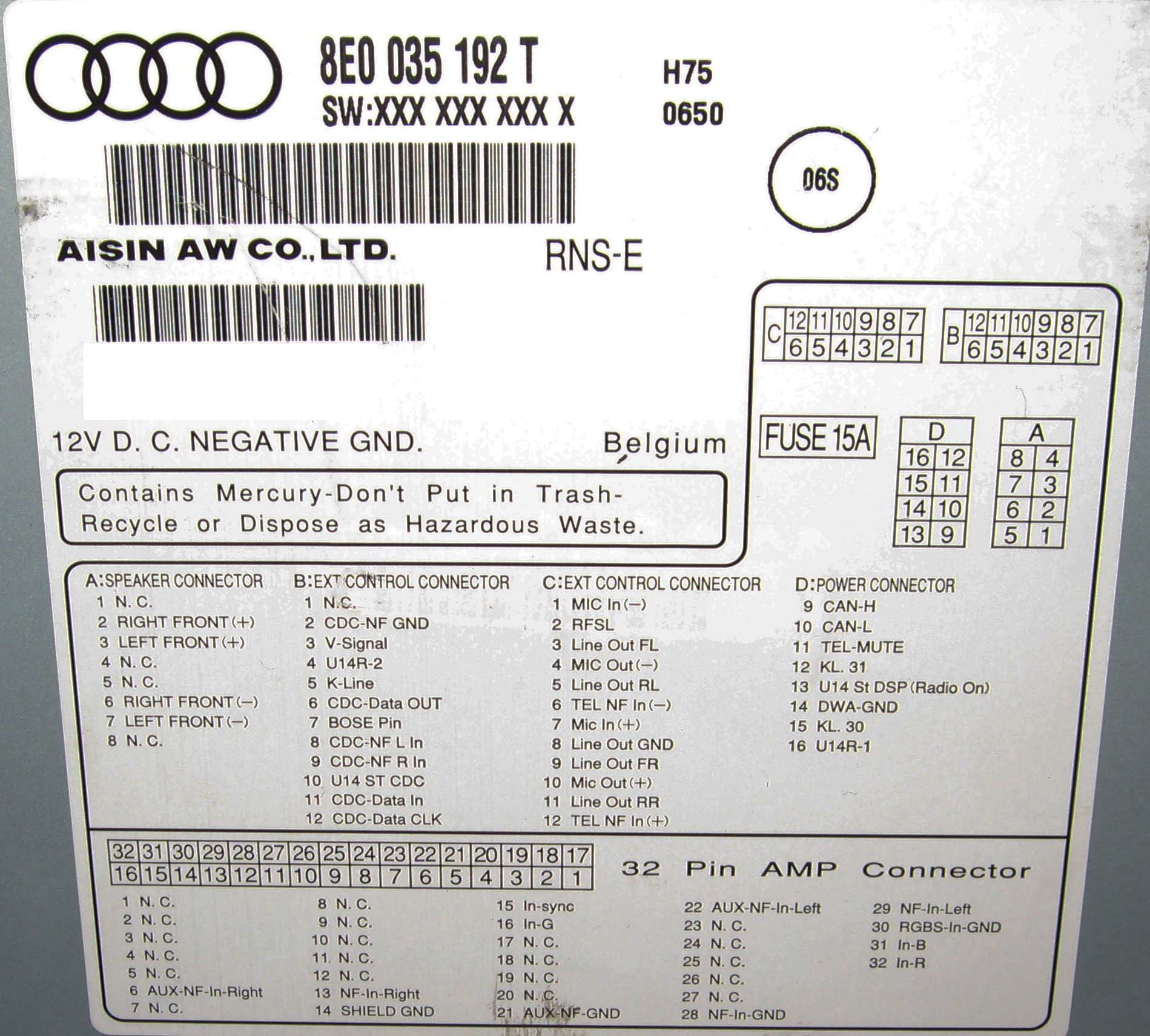
- If you ordered the cable for Navigation RNS-E you need to use the following
connecting scheme:
o green -> pin 12 Connector C (greeen NF+)
o black -> pin 6 Connector C (green NF -)
o grey -> Pin 11 Connector D (Mute)
o black/white -> CAN-Hi Pin 9 (connect to existing wires)
o black/green -> CAN-Lo Pin 10 (connect to existing wires)
- If you got the BNS-Navigation installed, you need to use the following
connecting scheme â these wires will be connected to the 20-pole connector at
your navigation-system.
o Pin 16 -> Green
o Pin 17 -> Grey
o Pin 19 -> Black
The interface is located under the passengers seat in a black box. You need to
remove all foam in order to be able to place the box down there.
Removing the cover of the steering wheel:
- Remove 2 lower screws
- Pull the cover
- Unconnect all connectors (diagnosis, light switch, light etc.)
Removing of the cluster unit:
- pull the cover
- remove the 2 screws
- pull the cluster unit out and unconnect the blue connector
After installation you need to recode your components:
- Radio (Chorous, Concert, Symphonie). Add 2 to the second digit of the right
side
- RNS-E Navigation: Add 2 for Temic (8 for Comfort controlling) to the 3rd digit
from the right side.
So, basically i'm looking for a bit of clarification on what connections i need to be making, as far as i knew it was power, earth and then connections to the RNSE, whereas these instructions also make reference to colour code of cables and also removing the instrument cluster??
I have no other connector plugs other than those on the loom supplied, do i need another connector?
Any help from someone who's been there would be beneficial.
cheers for any help
Graeme
Well, i thought it was just going to be a straight plug and play, or maybe a slight variation on that but it seems it may not be.
The kit i have so far is:-
BT control unit 8P0 862 335 Q
BT aerial ( came fitted to control unit)
BT microphone 8L1 862 373 A
Kufatec loom item 33866 (bluetooth handsfree harness)
Kufatec instructions
The loom itself looks ok , 2 plugs, one for the control unit and one for the mic, a red/wht cable for fuse s32-34
(+12v) an earch cable (brown ring terminal) and then there are 6 grey wires with printed idents along their length.
can hi, can low and diagnostic (in german) all have bare ends, ie no crimped connection
NF+, NF- and mute (in german) all have crimped ends.
The instructions from Kufatec are as follows:-
Installation guide Bluetooth hands free wiring harness Audi A4 8E
First of all: unconnect the carâs battery at the beginning of your work!
- 3-pole connector including the FAKRA connector will be connected to the
compensor.
- 2-pole connector will be connected to the microphone
- 10-pole red connector (only for radio) will be connceted to the radio (empty slot)
- Black/white â can high â connect to 20-pole mini iso connector pin 7
- Black/green â can low â connect to 20-pole mini iso connector pin 12
- Brown â ground
- Red / white fuse S 32-34 (+12V)
- Yellow â diagnosis â connect to 8 pole radio-connector pin 3
- If you ordered the cable for Navigation RNS-E you need to use the following
connecting scheme:
o green -> pin 12 Connector C (greeen NF+)
o black -> pin 6 Connector C (green NF -)
o grey -> Pin 11 Connector D (Mute)
o black/white -> CAN-Hi Pin 9 (connect to existing wires)
o black/green -> CAN-Lo Pin 10 (connect to existing wires)
- If you got the BNS-Navigation installed, you need to use the following
connecting scheme â these wires will be connected to the 20-pole connector at
your navigation-system.
o Pin 16 -> Green
o Pin 17 -> Grey
o Pin 19 -> Black
The interface is located under the passengers seat in a black box. You need to
remove all foam in order to be able to place the box down there.
Removing the cover of the steering wheel:
- Remove 2 lower screws
- Pull the cover
- Unconnect all connectors (diagnosis, light switch, light etc.)
Removing of the cluster unit:
- pull the cover
- remove the 2 screws
- pull the cluster unit out and unconnect the blue connector
After installation you need to recode your components:
- Radio (Chorous, Concert, Symphonie). Add 2 to the second digit of the right
side
- RNS-E Navigation: Add 2 for Temic (8 for Comfort controlling) to the 3rd digit
from the right side.
So, basically i'm looking for a bit of clarification on what connections i need to be making, as far as i knew it was power, earth and then connections to the RNSE, whereas these instructions also make reference to colour code of cables and also removing the instrument cluster??
I have no other connector plugs other than those on the loom supplied, do i need another connector?
Any help from someone who's been there would be beneficial.
cheers for any help
Graeme
 , it seems that by putting it all down in text in front of me has drawn my attention to some bits of the instructions i had missed before.