DRL BI XENON 2010 Wiring ( 2010 CEMC MODULe) PLEASE HELP

Chris Coates

Registered User
Joined
May 27, 2012
Messages
96
Reaction score
3
Points
8
Location
NULL
Hi All need help wireing up a 2010 a3 2L TDI ( i have the 2010 CEM Module with A B C On It) trying to wireup
DRL Bi Xenon headlights from halogens, have all the headlights installed and wired up with the Kufatec loom, but not sure on the A B C pin outs and how they should be wired up, and can only find info on Pre 2010 module, as the module changed in 2010 a3s and onwards,
PLEASE PLEASE HELP - ANY HELP WOULD BE SO GREAT THANK U
 
Hey mate. I've been trying to trace this wiring as well and looks like we have the same CECM. The part number of my CECM is 8P0 907 063A. The connectors/pin out diagram of our CECM should look liek this:

CECM8P0907063AConnectors.jpg


Based on my trace (which I recorded on a spreadsheet), the following appears to be the pin assignments to wire the bi-xenon/DRL headlights. Please disregard the "adapter" columns as my adapter is the wrong one and I'm in the process of swapping pins to make it work. You would be interested in the CECM assignment only. These are based off Elsawin.

Pin Number
Halogen Headlights
Bi-xenon Headlights
Driver side - 10 pin connector at end of loom
Adapter - 10 pin connector
Pin assignment
CECM assignment
Passenger side - 10 pin connector at end of loom
Adapter - 10 pin connector
Pin assignment
CECM assignment
Driver side - 14 pin connector
Adapter - 14 pin connector
Pin assignment
CECM assignment
Passenger side - 14 pin connector
Adapter - 14 pin connector
Pin assignment
CECM assignment
1
black/yellow (thin)
Headlight range control motor right
black/white (thin)
Headlight range control left
Headlight range control
2
grey/yellow (thin)
Headlight range control motor right
grey/yellow (thin)
Headlight range control left
Headlight range control
3
brown (thick)
white (thin) goes to Pin 14 of 14-pin connector
Earth
brown (thick)
white (thin) goes to Pin 14 of 14-pin connector
Earth
Headlight range control
4
grey/red (thin)
DRL/sidelight right
T52a/8
grey/black (thin)
DRL/sidelight left
T52a/7
Headlight range control
5
brown (thick)
white (thick)
Earth
brown (thick)
white (thick)
Earth
brown (thick)
white (thick)
Earth
brown (thick)
white (thick)
Earth
6
yellow (thick)
white (thick)
Dipped beam right
T52c/52
yellow/black (thick)
white (thick)
Dipped beam left
T52a/11
yellow (thick)
white (thick)
Gas discharge control unit right
T52c/52
yellow/black (thick)
white (thick)
Gas discharge control unit left
T52a/11
7
brown (thick)
white (thick)
Earth
brown (thick)
white (thick)
Earth
brown (thick)
white (thick)
earth
brown (thick)
white (thick)
Earth
8
white (thick)
white (thin)
goes to Pin 12 of 14-pin connector

Main/high beam right
T52c/46
white/black (thick)
white (thin)
goes to Pin 12 of 14-pin connector

Main/high beam left
T52a/5
9
black/green(?) (thin)
white (thick)
Turn signal right
T52c/50
black/white (thin)
white (thick)
Turn signal left
T52a/10
black/green (thin)
white (thick)
Turn signal right
T52c/50
black/white (thin)
white (thick)
Turn signal left
T52a/10
10
blue/grey (thin)
grey (thin)
LED DRL and sidelight right
T52a/8
blue/grey (thin)
grey (thin)
LED DRL and sidelight left
T52a/7
11
blue/red (thin)
grey (thin)
Dipped beam screen motor right
T52c/49
blue/red (thin)
grey (thin)
Dipped beam screen motor left
T52c/48
12
green/red (thin)
white (thin) from Pin 8 of 10-pin connector
LED DRL and sidelight right
T52a/44
grey/black (thin)
white (thin) from Pin 8 of 10-pin connector
LED DRL and sidelight left
T52c/26
13
white (thin)
Sidelight bulb right
T52c/46
black/white (thin)
Sidelight bulb left
T52a/5
14
white (thin) from Pin 3 of 10-pin connector
 
Last edited:
Saw this post from the Audizine forums. The labels on the 4 wires that gets wired into the CEM in the 2010+ Kufatec halogen-to-bixenon harness/adapter is consistent with the pin assignments that I traced in Elsawin for the Dipped beam screen motor and LED DRL and sidelight.

I'm still waiting for repair wires/connectors (to fix the eff'ed up adapters that I got) and new ballasts for my headlights so haven't got to testing the above wiring. Will update once I've done it and will try to post pics as well.

Inputs from those who have done this retrofit for the 8P3 with the 8P0 907 063A CEM would be appreciated.

Do you have these same labels that I have on the wires for the harness


Wire 1: Stecker C 26
Wire 2: Stecker C 48
Wire 3: Stecker C 49
Wire 4: Stecker A 44


He thinks it translates to:


Wire 1: plug C pin 26
Wire 2: plug C pin 48
Wire 3: plug C pin 49
Wire 4: plug A pin 44
 
I connected VCDS, went into 09 Cent Elect and used the long coding helper to find the bytes that have got bi-xenon options in it. I've taken screenshots of those and have posted them below.

At the moment, I'm using the process of elimination to test that everything in the headlights works before I actually install them on the car.

So far, I've plugged the headlights to the car using the adapter and so far have only confirmed that the turn signal lights works - makes sense that it should work without coding as both the halogen and bi-xenon current flow diagrams in Elsa have got this connected to T52c/50 and T52a/10 in the CEM.

At the moment, I highly suspect that the ballasts are dead. I've got new D3S bulbs fitted to the headlights. However when I plugged the headlights to the car (without coding), the dipped beams did not even fire up for a few seconds and just gave me errors on the DIS saying that headlights are out. From the Elsa diagrams, the halogen and bi-xenon CEM pin assignments for dipped beams (gas discharge control unit for the bi-xenon) are T52c/52 and T52a/11.

Questions:
(1) By coding the car to bi-xenons, in theory, the dipped beams should light up even if I havent wired in the 4 extra wres for the LED DRL and main beam shutters into the CEM right?

(2) Coding, should it be the following:
Byte 14: Bit 3 - Bi-xenon Headlights (with Shutter) installed = ON/checked
Byte 17: Bit 2 - Bi-xenon Headlights (with Shutter) w/o additional High Beams installed = ON/checked
Byte 18: Help... which option shoud I pick? I'm guessing either 2B or 2c should work?
Byte 27: Bit 2 - LED-Daytime Running Light (DRL) Module for parking/Position Light & Daytime Running Light (DRL) = ON/checked

Any assistance would be appreciated.

Byte14_zps8b34cd0d.jpg


Byte17_zps0bf1fd72.jpg


Byte18_zps7a9382ac.jpg


Byte27_zps23ff5335.jpg
 
I connected VCDS, went into 09 Cent Elect and used the long coding helper to find the bytes that have got bi-xenon options in it. I've taken screenshots of those and have posted them below.

At the moment, I'm using the process of elimination to test that everything in the headlights works before I actually install them on the car.

So far, I've plugged the headlights to the car using the adapter and so far have only confirmed that the turn signal lights works - makes sense that it should work without coding as both the halogen and bi-xenon current flow diagrams in Elsa have got this connected to T52c/50 and T52a/10 in the CEM.

At the moment, I highly suspect that the ballasts are dead. I've got new D3S bulbs fitted to the headlights. However when I plugged the headlights to the car (without coding), the dipped beams did not even fire up for a few seconds and just gave me errors on the DIS saying that headlights are out. From the Elsa diagrams, the halogen and bi-xenon CEM pin assignments for dipped beams (gas discharge control unit for the bi-xenon) are T52c/52 and T52a/11.

Questions:
(1) By coding the car to bi-xenons, in theory, the dipped beams should light up even if I havent wired in the 4 extra wres for the LED DRL and main beam shutters into the CEM right?

(2) Coding, should it be the following:
Byte 14: Bit 3 - Bi-xenon Headlights (with Shutter) installed = ON/checked
Byte 17: Bit 2 - Bi-xenon Headlights (with Shutter) w/o additional High Beams installed = ON/checked
Byte 18: Help... which option shoud I pick? I'm guessing either 2B or 2c should work?
Byte 27: Bit 2 - LED-Daytime Running Light (DRL) Module for parking/Position Light & Daytime Running Light (DRL) = ON/checked

Any assistance would be appreciated.


The low beams should come on regardless of coding as they are wired into the same position so for that check your ballasts.
Wire in the adapter as well as it will throw up errors and refuse to work if they are not wired in properly.

I would suggest that you code byte 14 bit 3, byte 18 to 2b and byte 27 bit 2 and then save that. If that doesnt work then go back in and uncheck byte 14 bit 3 and this time check byte 17 bit 2.
I know from my headlights that i cant have both checked at the same time as it will throw up an error on VCDS.

the difference from byte 18 2b and 2c from what i can see is that one only lights up the LED DRL on the front and the other lights up both the front and rear LEDs. but you can play with these options.

remember that you will need to clear all faults before you switch on the lights to test as i have had issues where due to the errors still flagged up the lights would not behave.
 
Sounds good Ash. Thanks for that. Will try coding it first then test again - that is after I have repinned my adapter which is for a pre-facelift model. If the test proves that the ballasts are indeed dead, will order new ones and well, wait for a couple more weeks to test it again.


I might wire the 4 extra wires (main beam shutter and LED DRL triggers) into the CEM as well without bolting the headlights in place in the car to check that everything works before installing everything permanently.


Will report back my findings. I intend to keep it in this thread to hopefully help others who are doing this retrofit to a 8P3 with the 8P0 907 063A CEM as I haven't seen a thread that confirmed wiring and coding for these models.
 
So I was sold a halogen to bixenon adapter for a pre-facelift A3 (8P1/8P2) for my 8P3. I just spent a few hours looking closely at Elsawin and comparing the current flow diagrams of a halogen-wired and bixenon-wired 8P3 to figure out how I can re-pin the adapter to suit a 8P3. I found out that a few pins will have to be moved to different pin locations in the 10-pin connector and 14-pin connector ends of the adapter to make it work - I've recorded this in a spreadsheet to guide me in the actual re-pinning and I've pasted a copy of the table below. Please note that this table supersedes the table that I pasted in Post #3 above.

I've also logged the wire sizes (in square millimetre I believe?) and wire colours from Elsawin for both the halogen-wired and bixenon-wired 8P3. I noticed that the wires that are currently connected to the CEM of my halogen-equipped 8P3 are mostly smaller than the wires required for a bixenon-equipped car. Specifically:

Dipped beam: halogen = 1.0, bixenon = 1.5 (connected to T52c/52 and T52a/11 in the CEM)
Turn signal: halogen = 0.35, bixenon = 0.5 (connected to T52c/50 and T52a/10 in the CEM)
DRL/sidelight halogen = 0.35, LED module for DRL and sidelight bixenon = 0.5 (connected to T52a/8 and T52a/7 in the CEM)

Now this has got me worried. For the above 3, the existing wires from the CEM to the end of the headlight wiring loom (10-pin connector) are smaller that what is required for the bixenons. Is there a risk of burning these smaller wires if I fit bixenon headlights? As from what I've read here, coding the car changes the functions/current of various pins from the CEM and based on the bixenon wires being bigger than those for the halogen, it probably indicates that more current will now be going out of those same CEM pins? Out of logic, that risk is more likely to happen as the above 3 lights are frequently used.

Help requested from those who have done this retrofit from before.


Pin NumberHalogen HeadlightsBi-xenon Headlights
Driver side - 10 pin connector at end of loomAdapter - 10 pin connectorPin assignmentElsawin CEM pin assignment
wire size/colour
Passenger side - 10 pin connector at end of loomAdapter - 10 pin connectorPin assignmentElsawin CEM pin assignment
wire size/colour
Driver side - 14 pin connectorAdapter - 14 pin connectorPin assignmentElsawin CEM pin assignment
wire size/colour
Passenger side - 14 pin connectorAdapter - 14 pin connectorPin assignmentElsawin CEM pin assignment
wire size/colour
1black/yellow (thin) Headlight range control motor right black/white (thin) Headlight range control left Headlight range control Headlight range control
2grey/yellow (thin) Headlight range control motor right grey/yellow (thin) Headlight range control left Headlight range control Headlight range control
3brown (thick)reuse between Pin 4 of 10-pin connector and Pin 10 of 14-pin connector; WILL BECOME VACANTHeadlight range control motor right - Earth brown (thick)reuse between Pin 4 of 10-pin connector and Pin 10 of 14-pin connector; WILL BECOME VACANTHeadlight range control motor left - Earth Headlight range control Headlight range control
4grey/red (thin)accept reused white thin wire from Pin 10 of 14-pin connectorDRL/sidelight rightT52a/8
0.35 grey/red
grey/black (thin)accept reused white thin wire from Pin 10 of 14-pin connectorDRL/sidelight leftT52a/7
0.35 grey/black
Headlight range control Headlight range control
5brown (thick)white (thick)Earth1.0 brownbrown (thick)white (thick)Earth1.0 brownbrown (thick)white (thick)Earth1.5 brownbrown (thick)white (thick)Earth1.5 brown
6yellow (thick)white (thick)Dipped beam rightT52c/52
1.0 yellow
yellow/black (thick)white (thick)Dipped beam leftT52a/11
1.0 yellow/black
yellow (thick)white (thick)Gas discharge control unit rightT52c/52
1.5 yellow
yellow/black (thick)white (thick)Gas discharge control unit leftT52a/11
1.5 yellow/black
7brown (thick)white (thick)Earth1.0 brownbrown (thick)white (thick)Earth1.0 brownbrown (thick)white (thick)Earth1.0 brownbrown (thick)white (thick)Earth1.0 brown
8white (thick)white (thin)
goes to Pin 12 of 14-pin connector; should move to Pin 13 of 14-pin connector
Main/high beam rightT52c/46
1.0 white
white/black (thick)white (thin)
goes to Pin 12 of 14-pin connector; should move to Pin 13 of 14-pin connector
Main/high beam leftT52a/5
1.0 black/white
9black/green(?) (thin)white (thick)Turn signal rightT52c/50
0.35 black/green
black/white (thin)white (thick)Turn signal leftT52a/10
0.35 black/white
black/green (thin)white (thick)Turn signal rightT52c/50
0.5 black/green
black/white (thin)white (thick)Turn signal leftT52a/10
0.5 black/white
10 blue/grey (thin)thin grey wire to go to Pin 4 of 10-pin connector; replace with short thin white wire that goes between Pin 3 of 10-pin connector and Pin 14 of 14-pin connectorLED module for DRL and sidelight rightT52a/8
0.5 blue/grey
blue/grey (thin)thin grey wire to go to Pin 4 of 10-pin connector; replace with short thin white wire that goes between Pin 3 of 10-pin connector and Pin 14 of 14-pin connectorLED module for DRL and sidelight leftT52a/7
0.5 blue/grey
11 blue/red (thin)grey (thin) extra wire to go to CEMDipped beam screen motor rightT52c/49
0.35 blue/red
blue/red (thin)grey (thin) extra wire to go to CEMDipped beam screen motor leftT52c/48
0.35 blue/red
12 green/red (thin)white (thin) from Pin 8 of 10-pin connector; to be replaced with grey (thin) extra wires removed from Pin 10 of 14-pin connector; then connect to CEMLED module for DRL and sidelight rightT52a/44
0.35 grey/red
grey/black (thin)white (thin) from Pin 8 of 10-pin connector; to be replaced with grey (thin) extra wires removed from Pin 10 of 14-pin connector; then connect to CEMLED module for DRL and sidelight leftT52c/26
0.35 grey/black
then connect to CEM then connect to CEM
13 white (thin)accept pin moved from Pin 12 of 14-pin connectorSidelight bulb rightT52c/46
0.5 white
black/white (thin)accept pin moved from Pin 12 of 14-pin connectorSidelight bulb leftT52a/5
0.5 black/white
14 reuse between Pin 4 of 10-pin connector and Pin 10 of 14-pin connector; WILL BECOME VACANT reuse between Pin 4 of 10-pin connector and Pin 10 of 14-pin connector; WILL BECOME VACANT
 
dont worry about the wire thickness, its just the recommended thickness which doesnt cause issues as its not that much thinner.
you look like you have sussed out the wiring issue... you just need to test it all out and see if the LEDs light up. then it would be a case of replacing the ballasts
 
This project has been really slow as I've been really busy with work and was away on holidays. Since the last post, I've bitten the bullet and ordered new OEM ballasts. The busy work and being on holidays was a good time to wait for the ballasts. I've fitted the new ballasts and a small victory - the dipped beams now lights up! With errors on the DIS but happy that 1 piece of the puzzle has been solved.

Have swapped pins and wires on the adapter as well and have now re-wrapped them in OEM-style harness tape.

Pics to follow.

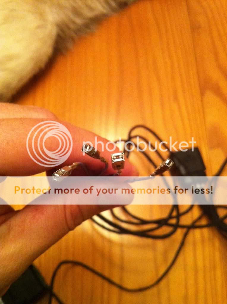
As the CEM module in my car have got the 3x 52-pin connectors, I've found that 1x pin connector out of the 4x loose wires that need to be wired to the CEM is different. I.e., 3 pin connectors are of the same size (same size as the 4 pins for the 2008 below adapters from Kufatec - same size connectors fitted to the VAG repair wire part number 000979150E) and the 4th pin connector has to be a bigger one. Here's a pic borrowed from a related thread in the audizine forums that shows 3 small pins and 1 big pin.

I don't have access to ETKA so can't find the part number for the bigger pin. Help on part number for this pin would be appreciated. Better yet, if anyone has a spare one, I would be keen to buy it from you so please do PM me.

*edit: It's the pin connector that's supposed to go to T52c/49.

IMG_0582.jpg
 
Last edited:
This project has been really slow as I've been really busy with work and was away on holidays. Since the last post, I've bitten the bullet and ordered new OEM ballasts. The busy work and being on holidays was a good time to wait for the ballasts. I've fitted the new ballasts and a small victory - the dipped beams now lights up! With errors on the DIS but happy that 1 piece of the puzzle has been solved.

Have swapped pins and wires on the adapter as well and have now re-wrapped them in OEM-style harness tape.

Pics to follow.

As the CEM module in my car have got the 3x 52-pin connectors, I've found that 1x pin connector out of the 4x loose wires that need to be wired to the CEM is different. I.e., 3 pin connectors are of the same size (same size as the 4 pins for the 2008 below adapters from Kufatec - same size connectors fitted to the VAG repair wire part number 000979150E) and the 4th pin connector has to be a bigger one. Here's a pic borrowed from a related thread in the audizine forums that shows 3 small pins and 1 big pin.

I don't have access to ETKA so can't find the part number for the bigger pin. Help on part number for this pin would be appreciated. Better yet, if anyone has a spare one, I would be keen to buy it from you so please do PM me.

*edit: It's the pin connector that's supposed to go to T52c/49.

IMG_0582.jpg
Hello,
Looks like I also have a similar ecm part number 8P0 907 063 K in a 2011 a3 USA. I bought a wiring harness off eBay, only has two thin wires to run to ecm for high beam shutter. I think it is wired wrong, as some Pins don't seem to all line up properly.
I don't want to plug lights in with adapter and short circuit anything.

Was trying to look at your spreadsheet, but figured I would just ask you what wire locations in the 10 and 14 pin adapters did you end up with?
Want to double check my adapter as it is.
Thanks for any help
 
Studied Elsa and this is what I come up with:

10 PIN adapter 14 PIN adapter
Pin 1-3 empty. 1-4 pin empty unless adaptive?
Pin 4---DRL/parking----10 pin led power
Pin 5------Ground--------5 pin ground
Pin 6------lowbeam------6 pin Hid power
Pin 7------Ground--------7 pin ground
Pin 8-------Highbeam----13 pin side markers
Pin 9-------Turnsgnl------9pin turnsgnl
Pin 10-----Sidemarker----12 pin DRL/parklmp/led

I mapped the wire connections and matched up what went to what spots on the 52 pin connectors on the module.
It seems to match up to my headlight and 10 pin on car, but looks a bit different than your wiring charts, or your choice of wire placement.?

The current high beam going to the side markers on xenons is only thing is goofy to me, but t52 c/46 & t52 a/5 match to the designations for the side markers.
Any input would be great!
Thanks
 
Hello,
Looks like I also have a similar ecm part number 8P0 907 063 K in a 2011 a3 USA. I bought a wiring harness off eBay, only has two thin wires to run to ecm for high beam shutter. I think it is wired wrong, as some Pins don't seem to all line up properly.
I don't want to plug lights in with adapter and short circuit anything.

Was trying to look at your spreadsheet, but figured I would just ask you what wire locations in the 10 and 14 pin adapters did you end up with?
Want to double check my adapter as it is.
Thanks for any help

The adapter should have 4 loose wires that needs to be wired to the ECM. Your adapter have got 2 only so it doesn't sound right.

Here's a simplified version of my spreadsheet showing the pin assignments in both the 10 and 14 pin connectors. I made the font colours the same to help trace where a pin in the 10-pin connector ends up on the other end at the 14-pin connector.

Not sure if the US A3 8P3 has the same wiring as the euro spec 8P3 (what we get here in Australia) but hopefully it will help you. As I said in my posts above, I carefully studied Elsa wiring diagrams for both halogen and bi-xenon. I.e., 2 diagrams then I matched them up. I strongly suggest that you use a spreadsheet as it will help you a lot. It did help me and in fact mine are now working! Just did it the past weekend.

Pin NumberHalogen HeadlightsBi-xenon Headlights
Pin assignmentElsawin CEM pin assignment
wire size/colour
Pin assignmentElsawin CEM pin assignment
wire size/colour
Pin assignmentElsawin CEM pin assignment
wire size/colour
Pin assignmentElsawin CEM pin assignment
wire size/colour
1Headlight range control motor right Headlight range control left Headlight range control Headlight range control
2Headlight range control motor right Headlight range control left Headlight range control Headlight range control
3Headlight range control motor right - Earth Headlight range control motor left - Earth Headlight range control Headlight range control
4DRL/sidelight rightT52a/8
0.35 grey/red
DRL/sidelight leftT52a/7
0.35 grey/black
Headlight range control Headlight range control
5Earth1.0 brownEarth1.0 brownEarth1.5 brownEarth1.5 brown
6Dipped beam rightT52c/52
1.0 yellow
Dipped beam leftT52a/11
1.0 yellow/black
Gas discharge control unit rightT52c/52
1.5 yellow
Gas discharge control unit leftT52a/11
1.5 yellow/black
7Earth1.0 brownEarth1.0 brownEarth1.0 brownEarth1.0 brown
8Main/high beam rightT52c/46
1.0 white
Main/high beam leftT52a/5
1.0 black/white
9Turn signal rightT52c/50
0.35 black/green
Turn signal leftT52a/10
0.35 black/white
Turn signal rightT52c/50
0.5 black/green
Turn signal leftT52a/10
0.5 black/white
10 LED module for DRL and sidelight rightT52a/8
0.5 blue/grey
LED module for DRL and sidelight leftT52a/7
0.5 blue/grey
11 Dipped beam screen motor rightT52c/49
0.35 blue/red
Dipped beam screen motor leftT52c/48
0.35 blue/red
12 LED module for DRL and sidelight rightT52a/44
0.35 grey/red
LED module for DRL and sidelight leftT52c/26
0.35 grey/black
13 Sidelight bulb rightT52c/46
0.5 white
Sidelight bulb leftT52a/5
0.5 black/white
14

I mapped the wire connections and matched up what went to what spots on the 52 pin connectors on the module.
It seems to match up to my headlight and 10 pin on car, but looks a bit different than your wiring charts, or your choice of wire placement.?

My spreadsheet and wire placement were not “my choice”. I based them off Elsa. I had to do it as I got the up-to-2009 adapter and had to re-pin it to update it to a 2010+ adapter (rather than throw the wrong adapter away, I spent about $15 more for repair wires and converted it to suit my 8P3).
 
As the CEM module in my car have got the 3x 52-pin connectors, I've found that 1x pin connector out of the 4x loose wires that need to be wired to the CEM is different. I.e., 3 pin connectors are of the same size (same size as the 4 pins for the 2008 below adapters from Kufatec - same size connectors fitted to the VAG repair wire part number 000979150E) and the 4th pin connector has to be a bigger one. Here's a pic borrowed from a related thread in the audizine forums that shows 3 small pins and 1 big pin.

I don't have access to ETKA so can't find the part number for the bigger pin. Help on part number for this pin would be appreciated. Better yet, if anyone has a spare one, I would be keen to buy it from you so please do PM me.

*edit: It's the pin connector that's supposed to go to T52c/49.

IMG_0582.jpg

Finally done! First off, in case anyone will need them, the part numbers for the repair wires that will get the above connectors for the 4 loose wires. I.e., 1 x repair wire will get you 2 pins (1 at each end of the wire).

3x small pins: 000979150E

1x big pin: 000979151E
 
  • Like
Reactions: dp_motley
(2) Coding, should it be the following:
Byte 14: Bit 3 - Bi-xenon Headlights (with Shutter) installed = ON/checked
Byte 17: Bit 2 - Bi-xenon Headlights (with Shutter) w/o additional High Beams installed = ON/checked
Byte 18: Help... which option shoud I pick? I'm guessing either 2B or 2c should work?
Byte 27: Bit 2 - LED-Daytime Running Light (DRL) Module for parking/Position Light & Daytime Running Light (DRL) = ON/checked

Any assistance would be appreciated.

Byte14_zps8b34cd0d.jpg


Byte17_zps0bf1fd72.jpg


Byte18_zps7a9382ac.jpg


Byte27_zps23ff5335.jpg

The coding that I used are as follows, everything working correctly as per factory functions including auto-lights and coming/leaving home lights and no errors on the DIS:

Byte 14: Bit 3 - Bi-xenon Headlights (with Shutter) installed = ON/checked

Byte 17: Bit 2 - Bi-xenon Headlights (with Shutter) w/o additional High Beams installed = ON/checked

Byte 18: Either 2B or 2C works. I picked 2C as I prefer to run the rear LEDs as DRLs as well. 2B will be front LED DRLs only.

Byte 27: Bit 2 - LED-Daytime Running Light (DRL) Module for parking/Position Light & Daytime Running Light (DRL) = ON/checked
 
Last edited:
  • Like
Reactions: dp_motley
And the proof that it works - here's a photo of the car with the DRL on (full brightness).

Haven't taken pics of the other functions but they work as follows:

Switch on "AUTO": Front and rear LEDs ON during daylight; headlights ON at dusk/dark with front LEDs dimmed; DRL dims when turn indicator is activated (during daylight when front DRLs are at full brightness)

Switch on park/sidelights: Front and rear LEDs ON but front LEDs are dimmed

Switch on headlight-ON: headlights ON with front LEDs dimmed

IMG_3096-Copy_zpsaedd3dad.jpg
 
Looking good mate! glad you finally got it sorted out :)

Hello,
Looks like I also have a similar ecm part number 8P0 907 063 K in a 2011 a3 USA. I bought a wiring harness off eBay, only has two thin wires to run to ecm for high beam shutter. I think it is wired wrong, as some Pins don't seem to all line up properly.
I don't want to plug lights in with adapter and short circuit anything.

Was trying to look at your spreadsheet, but figured I would just ask you what wire locations in the 10 and 14 pin adapters did you end up with?
Want to double check my adapter as it is.
Thanks for any help

you have the wrong adapter... that is the adapter for the prefacelift cars. you can repin it to suit your car but will take a bit of doing including some new repair pins
 
Looking good mate! glad you finally got it sorted out :)


you have the wrong adapter... that is the adapter for the prefacelift cars. you can repin it to suit your car but will take a bit of doing including some new repair pins
Thanks for the reply, but it looks like USA A3s are a bit different. I have a pin 10 in the stock 10 pin that is marked side marker lamps with designation T52 A/44 T52/ C26 that matches up to 12 pin of 14 pin adapter. I should only need to run the high beam triggers to the ecm.
So I think it will work for my US car. I don't see a 10 pin in the above spreadsheet. Any input welcome.
 
The adapter should have 4 loose wires that needs to be wired to the ECM. Your adapter have got 2 only so it doesn't sound right.

Here's a simplified version of my spreadsheet showing the pin assignments in both the 10 and 14 pin connectors. I made the font colours the same to help trace where a pin in the 10-pin connector ends up on the other end at the 14-pin connector.

Not sure if the US A3 8P3 has the same wiring as the euro spec 8P3 (what we get here in Australia) but hopefully it will help you. As I said in my posts above, I carefully studied Elsa wiring diagrams for both halogen and bi-xenon. I.e., 2 diagrams then I matched them up. I strongly suggest that you use a spreadsheet as it will help you a lot. It did help me and in fact mine are now working! Just did it the past weekend.

Pin NumberHalogen HeadlightsBi-xenon Headlights
Pin assignmentElsawin CEM pin assignment
wire size/colour
Pin assignmentElsawin CEM pin assignment
wire size/colour
Pin assignmentElsawin CEM pin assignment
wire size/colour
Pin assignmentElsawin CEM pin assignment
wire size/colour
1Headlight range control motor rightHeadlight range control leftHeadlight range controlHeadlight range control
2Headlight range control motor rightHeadlight range control leftHeadlight range controlHeadlight range control
3Headlight range control motor right - EarthHeadlight range control motor left - EarthHeadlight range controlHeadlight range control
4DRL/sidelight rightT52a/8
0.35 grey/red
DRL/sidelight leftT52a/7
0.35 grey/black
Headlight range controlHeadlight range control
5Earth1.0 brownEarth1.0 brownEarth1.5 brownEarth1.5 brown
6Dipped beam rightT52c/52
1.0 yellow
Dipped beam leftT52a/11
1.0 yellow/black
Gas discharge control unit rightT52c/52
1.5 yellow
Gas discharge control unit leftT52a/11
1.5 yellow/black
7Earth1.0 brownEarth1.0 brownEarth1.0 brownEarth1.0 brown
8Main/high beam rightT52c/46
1.0 white
Main/high beam leftT52a/5
1.0 black/white
9Turn signal rightT52c/50
0.35 black/green
Turn signal leftT52a/10
0.35 black/white
Turn signal rightT52c/50
0.5 black/green
Turn signal leftT52a/10
0.5 black/white
10LED module for DRL and sidelight rightT52a/8
0.5 blue/grey
LED module for DRL and sidelight leftT52a/7
0.5 blue/grey
11Dipped beam screen motor rightT52c/49
0.35 blue/red
Dipped beam screen motor leftT52c/48
0.35 blue/red
12LED module for DRL and sidelight rightT52a/44
0.35 grey/red
LED module for DRL and sidelight leftT52c/26
0.35 grey/black
13Sidelight bulb rightT52c/46
0.5 white
Sidelight bulb leftT52a/5
0.5 black/white
14


My spreadsheet and wire placement were not “my choice”. I based them off Elsa. I had to do it as I got the up-to-2009 adapter and had to re-pin it to update it to a 2010+ adapter (rather than throw the wrong adapter away, I spent about $15 more for repair wires and converted it to suit my 8P3).
Thanks for the reply. The color spreadsheet is much easier to understand what wires go where, thank you.
Like I posted, USA A3s seem to have a side marker lamp (pin 10) that match up to pin 12 of 14 pin in current Elsawin. So high beam trigger is only thing I need to run to ecm.

Am I correct that you have no pin in spot 10 of stock 10 pin?

Glad your light are working, they look great.
Thanks for your help, I'll hope to install this weekend, wish me luck.

Yes, 10 was vacant.
 
help needed pls:
audi a3 2011 1.6 tdi

issue i have is that the drls dont seem to light up i have coded the car as to the above settings and have played around and changed up a few to try and make them work but nothing..
ive looked at the 10 pin plug and tested it and what i have found is that the drl wire in my car does go to the correct pin on the adaptors at first i thought the adaptors were wrong but i have figured out that for the drls to work there needs to be another live connected to the headlight for the drls to light up, so in essence pin 4>10 is correct but i have no power going into pin 12 now can i just put a ignition live into this or should it be like pin 4 and be switching when i turn drls on?

the only error codes i have coming up are DRL`s now so everything else seems right before coding i used to get dipped beams one aswell
 
^ There's a lot of information that you need to confirm for us to be able to help you out. Looks like a wiring problem.

1. Do you have the same CE module as mine (8P0 907 063A). As your car is a 2011 and mine is a 2010, yours may be different.

2. If yes to Item 1 above, have you checked that all your wiring are consistent with the table in Post #14? As you mentioned that you've got the correct adapter, the 4 extra/loose wires should have been wired into the CEM - have you done these as well? The CEM pin assignments in Post #4 were correct for my car.

Not able to advise if a live ignition feed will do it as I never went that way and wired mine by "merging" the Elsa wiring diagrams for a halogen-equipped and bixenon-equipped car then wiring it accordingly.

thanks for the reply pal heres the info:

1.yes exactly the same ecm as yours 3*52 pin plug

2. i think i have managed to figure out what the issue is "i have the wrong adaptor"basiclly im 1 wire short as i need a cable from my adaptor to run to A44/c26 for the leds and i assume its this cable that determines when the leds should be dimming or not as when i loop a wire over from pin 10 from my 14 pin lug and get some power to pin 12 from pin 10 they start working but just dont dim.
 
^ Well, looks like your close to nailing it then! Looks like you will just need to do the following:

Add the missing wires in your adapter (Pin 12 of the 14-connector), run these wires through the fire wall and slot the pins into A44 and C26 of the 52-pin connectors at the CEM.

The table in Post #7 above should be able to help you with this. Good luck and enjoy it mate. You're nearly there!
 
Okay so here I go sounding all thick but iv don't the convertion and basically wired the drl on the harness to the side light so that all works... All I'm struggling is we're to wire the high beams too its just the small 4 wires that come through the dash.

The big wires are DRLS (which I don't need coz I wires them to my side lights )
The small two wires (high beam) I don't have a clue where to wire them too ??

Once these small wires are connected I'm 99% sure it should work then as iv had vag com on it today and can't see any coding for it

can anyone help me please I'm stuck
 
the write up is pretty good much credit to the op it helped me out alot so dont see what you cant figure out its all there in black and white?
 
Right sorry for being so dumb but im really stuck with this now and its driving me insane !

iv dont the front end convertion and light convertion and wired my DRls to my side lights but my high beams still dont seem to want to work i dont know were to wire the 2 trigger wires too ?? I dont think my cemc module is the same as the one on this post but can seem to find anything on it :-/

my cemc module - 8p0 907 279

my a3 is a 2004 reg

please please please is there anyone who can share some light on this with me as im realy stuck and dont know what to do now ?

is it posibale that i have to buy a new cemc module and wire it in totally different ?
 
Sorry im dislexic. I think you can get the ajust of what im trying to ask so can you help me or not ? I thaugh this was a forum that people help each other out on not somwere to slate each other on if you can help me there is no point commenting
 
you contradict what your saying as if you read your own message you say you`ve wired the drls to the sidelights then you say you have for cables coming thru the dash ??
if you have a little bit of electrical knowledge then you may get away with doing it but if you dont then you better of paying someone to do the install for you as it can go very wrong very quick and also you have to have it all coded via vcds i would drop nhn a pm and speak to him regards installation.....
 
As you have already been advised the proper guide on how to do it is already on the forum as well as the wiring schematics.
But to be able to get the main beams working you need to have the right ce module, have the drl and shutter wires into the said ce module and CODE it for the xenons to work. Too many people nowadays seem to miss the coding part and think that by just wiring it they can get it to work.

As you have already stated your ce module part number I can confirm that you need a more up to date module and you would need to swap it over and recode it, which isn't a straightforward job!
If you do a bodge job and it doesn't work after then no point in complaining, best thing is to genome of us retrofitter a to complete the work for you
 
  • Like
Reactions: Yolo_8p3
Apologies for the bump, but can anyone confirm if my CECM needs updating to retrofit these? I've got an 8p0 907 063N CECM and when I go into the long code I seem to have the xenon options like in the screenshots above.

The car is a 2011 s-line 170tdi.

Cheers.
 
hi everyone! i'm going to bump this thread since i had some problems retrofitting mine :(

i've done everything the thread says.
in the long coding i've changed and put the same settings @jpestrada115 did, and it should work. i placed the cables in the pins that the cables said (A44 C26 C48 and C49 if i'm not wrong), and the LEDs and high beams are not working
and get the same errors in vagcom.

so i am wondering, do i need a new module capable of recognizing led and bixenon? (http://www.bks-tuning.com/audi-a3-8p-tt-8j-r8-control-unit-xenoncentral-electric.html)

sorry i didnt get to write down the error codes or the number part of my ECU.

any help is appreciated!