

Wiring Bi xenon advice
- Thread starter ~RS~
- Start date
You are using an out of date browser. It may not display this or other websites correctly.
You should upgrade or use an alternative browser.
You should upgrade or use an alternative browser.
No the DRL wires are not fitted yet as said above I tried to push the ends of the larger DRL connections into the plug after breaking off the larger connector that is. This didn't activate the DRL's so I took the DRL wires out and tapped them up again. The module is in with all plugs swapped over.
I'll post the log now give me a sec
I'll post the log now give me a sec
So here are the 10 faults! This scan was taken when the DRL wires had been poked into the plug (without connector on).
Address 09: Cent. Elect. Labels: 8P0-907-279-30-H.lbl
Part No SW: 8P0 907 279 K HW: 8P0 907 279 K
Component: Bordnetz-SG H54 2501
Revision: 00H54000 Serial number: 00000007998692
Coding: F2061E8380141C004F1800001800000000084E0764250802000000000000
Shop #: WSC 06752 128 38088
Part No: 8P2 955 119 B
Component: Wischer AU350 H01 0130
Coding: 00062736
Shop #: WSC 06752
Part No: 4E0 910 557
Component: REGENLICHTSENSORH10 0050
Coding: 00150573
Shop #: WSC 06752
10 Faults Found
02394 - Parking Light Left Front (M1)
012 - Electrical Fault in Circuit
Freeze Frame:
Fault Status: 01101100
Fault Priority: 2
Fault Frequency: 1
Reset counter: 28
Mileage: 159212 km
Time Indication: 0
Date: 2011.04.19
Time: 16:45:00
Freeze Frame:
ON
Voltage: 12.05 V
ON
ON
OFF
OFF
OFF
02395 - Parking Light Right Front (M3)
012 - Electrical Fault in Circuit
Freeze Frame:
Fault Status: 01101100
Fault Priority: 2
Fault Frequency: 1
Reset counter: 28
Mileage: 159212 km
Time Indication: 0
Date: 2011.04.19
Time: 16:45:00
Freeze Frame:
ON
Voltage: 12.05 V
ON
ON
OFF
OFF
OFF
01259 - Fuel Pump Relay (J17)
009 - Open or Short to Ground
Freeze Frame:
Fault Status: 01101001
Fault Priority: 5
Fault Frequency: 1
Reset counter: 28
Mileage: 159212 km
Time Indication: 0
Date: 2011.04.19
Time: 16:45:00
Freeze Frame:
ON
Voltage: 12.10 V
ON
ON
OFF
OFF
OFF
00924 - Relay for Headlamp Cleaning System (J39)
009 - Open or Short to Ground
Freeze Frame:
Fault Status: 01101001
Fault Priority: 4
Fault Frequency: 1
Reset counter: 28
Mileage: 159212 km
Time Indication: 0
Date: 2011.04.19
Time: 16:45:00
Freeze Frame:
OFF
Voltage: 12.50 V
OFF
ON
OFF
OFF
OFF
01800 - Light Switch (E1)
008 - Implausible Signal - Intermittent
Freeze Frame:
Fault Status: 00101000
Fault Priority: 3
Fault Frequency: 2
Reset counter: 68
Mileage: 159212 km
Time Indication: 0
Date: 2011.04.19
Time: 16:45:00
Freeze Frame:
OFF
Voltage: 12.60 V
OFF
ON
OFF
OFF
OFF
01516 - Terminal 30; Left
011 - Open Circuit - Intermittent
Freeze Frame:
Fault Status: 00101011
Fault Priority: 1
Fault Frequency: 1
Reset counter: 68
Mileage: 159212 km
Time Indication: 0
Date: 2011.04.19
Time: 17:17:00
Freeze Frame:
OFF
Voltage: 12.60 V
OFF
ON
OFF
OFF
OFF
02403 - Terminal 15 for Interior
012 - Electrical Fault in Circuit
Freeze Frame:
Fault Status: 01101100
Fault Priority: 2
Fault Frequency: 1
Reset counter: 28
Mileage: 159212 km
Time Indication: 0
Date: 2011.04.19
Time: 16:45:00
Freeze Frame:
ON
Voltage: 12.05 V
ON
ON
OFF
OFF
OFF
00927 - Terminal 30 (Right)
011 - Open Circuit - Intermittent
Freeze Frame:
Fault Status: 00101011
Fault Priority: 1
Fault Frequency: 2
Reset counter: 68
Mileage: 159212 km
Time Indication: 0
Date: 2011.04.19
Time: 16:45:00
Freeze Frame:
OFF
Voltage: 12.60 V
OFF
ON
OFF
OFF
OFF
02745 - Bulb for Daytime Running Light; Left
010 - Open or Short to Plus
Freeze Frame:
Fault Status: 01101010
Fault Priority: 2
Fault Frequency: 1
Reset counter: 28
Mileage: 159212 km
Time Indication: 0
Date: 2005.09.13
Time: 31:63:63
Freeze Frame:
ON
Voltage: 12.50 V
ON
ON
OFF
OFF
OFF
02746 - Bulb for Daytime Running Light; Right
010 - Open or Short to Plus
Freeze Frame:
Fault Status: 01101010
Fault Priority: 2
Fault Frequency: 1
Reset counter: 28
Mileage: 159212 km
Time Indication: 0
Date: 2005.09.13
Time: 31:63:63
Freeze Frame:
ON
Voltage: 12.50 V
ON
ON
OFF
OFF
OFF
Last edited:
Well I'm a little bit at a loss, then cause you will get errors if wires arent connected, its an unavoidable issue until its fully wired, pointless coding until its all connected properly & why cant you trace the repair wires, that parts easy.
6 of those faults are obviously wiring, rest could be coding & relay/fuse positioning, until you have wires in place for all, then pointless asking us what the issues are.
I don't personally have elsa so couldn't verify the correct repair wires. My mate has it and is having a look into it but elsa is new to him so he's working out navigating his way around it.
I expected to still have the DRL faults but assumed that the rest would go away?? Could you be a diamond and help out with which repair wires are needed to get these bloomin DRL's sorted? Or where to look in elsa so I can give my mate some pointers...
I expected to still have the DRL faults but assumed that the rest would go away?? Could you be a diamond and help out with which repair wires are needed to get these bloomin DRL's sorted? Or where to look in elsa so I can give my mate some pointers...
Khufu
Registered User
i guess you coud try the 1st one on my list, its for a 0.5mm wire which is the size of wire used according to ELSA.


Khufu
Registered User
you need to go into current flow diagrams & look under xenon headlights. This shows you the colour & size of wires. If you then go into ETKA and look up the brown 11 pin connector and click on it you can then click on another icon that will show you suitable connectors for that connector
Cheers Khufu your a star ") I will get these wires sorted next week and see how I go from there after having a good look at these elsa diagrams
I will get these wires sorted next week and see how I go from there after having a good look at these elsa diagrams
Will I need to solder the old wire to new repair wire? Sorry for what might seem straightforward questions, as you can tell I'm out of my depth :Flush:
I will get these wires sorted next week and see how I go from there after having a good look at these elsa diagramsWill I need to solder the old wire to new repair wire? Sorry for what might seem straightforward questions, as you can tell I'm out of my depth :Flush:
Last edited:
Forgot to ask.... is the pin assignment the same across all of the central electric modules (04 - 08) except the new facelift ones? I found this and it maybe useful to anybody
thinking about having a stab at retrofitting xenon headlights

Connector A (11-pin)
Pin 1: Terminal 30 right
Pin 2: Dipped beam right
Pin 3: Main beam right
Pin 4: Fog light right
Pin 5: Vacant
Pin 6: Flasher front right
Pin 7: Side light front left
Pin 8: Flasher side left
Pin 9: Terminal 31 left
Pin 10: Electric fuel pump relay
Pin 11: Terminal 50 relay
Connector B (12-pin)
Pin 1: Reversing light right
Pin 2: Vacant
Pin 3: Light sensor supply
Pin 4: Fog tail light, left
Pin 5: Brake light right
Pin 6: Vacant
Pin 7: Footwell light
Pin 8: Vacant
Pin 9: Side light rear right
Pin 10: Rear right turn signal
Pin 11: Interior lighting
Pin 12: Terminal 58s
Connector C (12-pin)
Pin 1: Seat heating shut-off
Pin 2: Brake light left
Pin 3: Vacant
Pin 4: Coming Home LED
Pin 5: Vacant
Pin 6: Vacant
Pin 7: Vacant
Pin 8: Number plate light
Pin 9: Brake light centre
Pin 10: Side light rear left
Pin 11: Rear left turn signal
Pin 12: Vacant
Connector D (11-pin)
Pin 1: Terminal 30 left
Pin 2: Fog light left
Pin 3: Main beam left
Pin 4: Dipped beam left
Pin 5: Terminal 31 right
Pin 6: Vacant
Pin 7: Terminal 15 engine relay
Pin 8: Headlight washer relay
Pin 9: Flasher side right
Pin 10: Side light front right
Pin 11: Flasher front left
Connector E (16-pin)
Pin 1: Side lights switch
Pin 2: Brake light switch
Pin 3: Vacant
Pin 4: Vacant
Pin 5: Garage door opener input
Pin 6: Fog tail light switch
Pin 7: P/N without interlock switch
Pin 8: Dipped beam switch
Pin 9: Vacant
Pin 10: Vacant
Pin 11: Light sensor input
Pin 12: Coming Home potentiometer tap
Pin 13: Fog tail light switch
Pin 14: Assistance driving lights switch
Pin 15: EC mirror non-dipping
Pin 16: Light switch 0 setting
Connector F (8-pin)
Pin 1: Terminal 50 diagnosis
Pin 2: Terminal 15 engine diagnosis
Pin 3: LIN bus
Pin 4: Terminal L-alternator
Pin 5: Bonnet contact
Pin 6: Reversing light switch
Pin 7: Terminal 30 reference
Pin 8: Terminal 31 reference
Connector G (12-pin)
Pin 1: Terminal 50 switch
Pin 2: Hazard warning lights LED
Pin 3: Rear window heater LED
Pin 4: Terminal 58s potentiometer ground
Pin 5: Vacant
Pin 6: Rear window heater button
Pin 7: Convenience CAN Low
Pin 8: Convenience CAN High
Pin 9: Hazard warning lights button
Pin 10: Terminal 58s potentiometer supply
Pin 11: Terminal 15 switch
Pin 12: Terminal 58s potentiometer tap
Connector H (12-pin)
Pin 1: Vacant
Pin 2: Vacant
Pin 3: Vacant
Pin 4: Vacant
Pin 5: Vacant
Pin 6: Vacant
Pin 7: Vacant
Pin 8: Vacant
Pin 9: Vacant
Pin 10: Vacant
Pin 11: Vacant
Pin 12: Vacant
thinking about having a stab at retrofitting xenon headlights
Connector A (11-pin)
Pin 1: Terminal 30 right
Pin 2: Dipped beam right
Pin 3: Main beam right
Pin 4: Fog light right
Pin 5: Vacant
Pin 6: Flasher front right
Pin 7: Side light front left
Pin 8: Flasher side left
Pin 9: Terminal 31 left
Pin 10: Electric fuel pump relay
Pin 11: Terminal 50 relay
Connector B (12-pin)
Pin 1: Reversing light right
Pin 2: Vacant
Pin 3: Light sensor supply
Pin 4: Fog tail light, left
Pin 5: Brake light right
Pin 6: Vacant
Pin 7: Footwell light
Pin 8: Vacant
Pin 9: Side light rear right
Pin 10: Rear right turn signal
Pin 11: Interior lighting
Pin 12: Terminal 58s
Connector C (12-pin)
Pin 1: Seat heating shut-off
Pin 2: Brake light left
Pin 3: Vacant
Pin 4: Coming Home LED
Pin 5: Vacant
Pin 6: Vacant
Pin 7: Vacant
Pin 8: Number plate light
Pin 9: Brake light centre
Pin 10: Side light rear left
Pin 11: Rear left turn signal
Pin 12: Vacant
Connector D (11-pin)
Pin 1: Terminal 30 left
Pin 2: Fog light left
Pin 3: Main beam left
Pin 4: Dipped beam left
Pin 5: Terminal 31 right
Pin 6: Vacant
Pin 7: Terminal 15 engine relay
Pin 8: Headlight washer relay
Pin 9: Flasher side right
Pin 10: Side light front right
Pin 11: Flasher front left
Connector E (16-pin)
Pin 1: Side lights switch
Pin 2: Brake light switch
Pin 3: Vacant
Pin 4: Vacant
Pin 5: Garage door opener input
Pin 6: Fog tail light switch
Pin 7: P/N without interlock switch
Pin 8: Dipped beam switch
Pin 9: Vacant
Pin 10: Vacant
Pin 11: Light sensor input
Pin 12: Coming Home potentiometer tap
Pin 13: Fog tail light switch
Pin 14: Assistance driving lights switch
Pin 15: EC mirror non-dipping
Pin 16: Light switch 0 setting
Connector F (8-pin)
Pin 1: Terminal 50 diagnosis
Pin 2: Terminal 15 engine diagnosis
Pin 3: LIN bus
Pin 4: Terminal L-alternator
Pin 5: Bonnet contact
Pin 6: Reversing light switch
Pin 7: Terminal 30 reference
Pin 8: Terminal 31 reference
Connector G (12-pin)
Pin 1: Terminal 50 switch
Pin 2: Hazard warning lights LED
Pin 3: Rear window heater LED
Pin 4: Terminal 58s potentiometer ground
Pin 5: Vacant
Pin 6: Rear window heater button
Pin 7: Convenience CAN Low
Pin 8: Convenience CAN High
Pin 9: Hazard warning lights button
Pin 10: Terminal 58s potentiometer supply
Pin 11: Terminal 15 switch
Pin 12: Terminal 58s potentiometer tap
Connector H (12-pin)
Pin 1: Vacant
Pin 2: Vacant
Pin 3: Vacant
Pin 4: Vacant
Pin 5: Vacant
Pin 6: Vacant
Pin 7: Vacant
Pin 8: Vacant
Pin 9: Vacant
Pin 10: Vacant
Pin 11: Vacant
Pin 12: Vacant
Khufu
Registered User
you get a two ended repair wire like this:

the thickness of wire and type of end depends on what part number you order. Ordering one wire gives you two connectors.
I must say, at this point, i've got my bi-xenons in with a non-DRL headlight switch & an A rev CE module and i have no errors except for the highbeam. do all your lights actually work? What headlight switch you using as the wiring is different between the DRL headlight switch & the NON-DRL switch...

I had my C module wired up and the faults were pretty much the same, your lucky mate! It's like a ****** orchestra anytime I go for a spin with the amount of warnings going off
I am using a MK2 TT switch the same one NHN has fitted. TBH I hadn't given much thought to the wiring being different on the switches does that also need to be addressed? What will I need to do there then? As I said well out of my depth but trying to learn on the job... YTS lol
Thanks for that pic so you just use something to crimp that connector to the old bit of wire and bobs you uncle then.
Khufu
Registered User
I've just re-looked at wiring diagrams & i've had a squint - its a 1mm wire which is more likely a 000 979 150 E repair wire, sorry.
according to my wiring diagram - right DRL goes to T11c/3 (brown connector D) and left goes to T11b/3 (black connector A). Looking at your posted wiring there seems to be a problem as they are currently use by main beam & may explain why they are giving you errors?
for example, on the right hand light with bi-xenon:
dipbeam = T11b/2
Mainbeam = T11b/5
sidelight = T11c/10
DRL = T11b/3
so you may have to swap the wires about in the multplug to match up with a CE that supports DRLs?
Khufu
Registered User
I've a DRL switch too & it gives me errors too if i try to use it. I've put it aside till i get the CE module as using it puts the lights on all the time & the fog lights dont work.
Khufu your correct in you observation mate, I stuck the high beam triggers wires in the correct places I could find for but pin 3 on plug A and D were taken. The kufatec fitting instructions stated to to have high beam triggers in Plug A Pin 5 and Plug D pin 6 and the DRL's in the plugs you say they go in above. I didn't want to risk pulling the multiplug apart so I left them be.... So I will need to move this wiring about then  damn! Does elsa give direction as to what wire will go where in terms of colour or something or does that all need to worked out? I hope it's the former or it sounds like a nightmare!
Thanks a lot for your help mate it's much appreciated!!!
damn! Does elsa give direction as to what wire will go where in terms of colour or something or does that all need to worked out? I hope it's the former or it sounds like a nightmare! Thanks a lot for your help mate it's much appreciated!!!
Ok 1st you need to check the gauge of wires in elsawin, 2nd you need to get the part number of the connector, 3rd need to find the connector in etka, 4th additional info window icon under that connector part number will show the wires that fit into that connector, 5th the wires that are shown as valid for that connector show a gauge of wire for them, hence 1st point tallies up with the 5th.
As far as elsa is concerned, you have to go into your brand as in audi, year, chassis, engine code & gearbox code to show your wiring for your existing car, then you need to check for a car from 08-09 onwards what pins that needs connecting given the kit fitted newer, dont assume anything mate, use fact from elsawin & connect all wires then worry about coding & errors.
As far as elsa is concerned, you have to go into your brand as in audi, year, chassis, engine code & gearbox code to show your wiring for your existing car, then you need to check for a car from 08-09 onwards what pins that needs connecting given the kit fitted newer, dont assume anything mate, use fact from elsawin & connect all wires then worry about coding & errors.
Cheers Nige that makes it clearer. So if I got this correct, after finding correct gauge and connector, elsa will show my current wiring configuration to the ceb then I need to move the wires around to suit the configuration given for the facelift 08- wiring diagram in elsa for plugs A + D?
I remember you guys saying that the facelift module is wired totally different, does that mean that wires currently going into these plugs maybe located in different plugs?
I remember you guys saying that the facelift module is wired totally different, does that mean that wires currently going into these plugs maybe located in different plugs?
NHN said:Ok 1st you need to check the gauge of wires in elsawin, 2nd you need to get the part number of the connector, 3rd need to find the connector in etka, 4th additional info window icon under that connector part number will show the wires that fit into that connector, 5th the wires that are shown as valid for that connector show a gauge of wire for them, hence 1st point tallies up with the 5th.
As far as elsa is concerned, you have to go into your brand as in audi, year, chassis, engine code & gearbox code to show your wiring for your existing car, then you need to check for a car from 08-09 onwards what pins that needs connecting given the kit fitted newer, dont assume anything mate, use fact from elsawin & connect all wires then worry about coding & errors.
So I finally had a chance to have a look at elsa.... was baffled for a while but worked out what's what apart from the letter after code for example T11'b'/3.... Anyways... found the diagram khufu referred to a few posts back as seen below
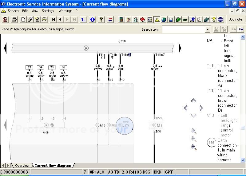
So it's definitely as he says a 10mm wire that is blue + grey iirc from the key at bottom of diagram. I can't seem to find a way to get the part number for the connector (smaller one I need). Hence stuck @ stage 2 on NHN's advice list quoted above...
The other thing I was wondering is will I need to go through each individual current flow diagram referring to anything lighting related for in the cem to find out if I need to move wires about or not... I am thinking that surely it will only be whatever is in currently in Plug A Pin 3 and Plug D Pin 3 - advised pins for DRL's. I'm going to have a look at my CEM now and take some pics to see what pins are free and what wires are going into plug a pin 3 and plug d pin 3.
But for the minute I am kinda overwhelmed, but not beaten... yet lol!
Any more advice would be stellar guys! I have a few bits that are being done this week and would be over the moon to put the icing on the cake in form of DRL's and no more ****** warning lights!
To add to my misery I noticed my washer jets or the pump isn't working/ or at least there is no noise or water coming from them but it's listed as fault code.... assuming it's also related to the change of module as was fine before now when wiper stalk is pulled back for water no water and all wipers front and rear go off!
 think an early beer may well be in order........
Khufu
Registered User
T11b is the connector id - ie 11 pin black connector (connector A on the CE module) and the 3 is the pin number on the connector. T11b looks the same as T11c but b is black & c is brown & the the connections on it are mirrored but both take the same size wires in the respective holes.
what i did was look in etka for brown and black 11 pin connectors:

from that you realise it must be item 13. Clicking on brings up an order window and a tab for additional information, clicking on this & scrolling down to look for repair wires that uses a 1mm wire, though there appears to be two size, maybe Nigel can help there....

The 1st option is the basic wire, the rest are special ones - ie gold or siver plated etc (ie more ££££ LOL)
what i did was look in etka for brown and black 11 pin connectors:
from that you realise it must be item 13. Clicking on brings up an order window and a tab for additional information, clicking on this & scrolling down to look for repair wires that uses a 1mm wire, though there appears to be two size, maybe Nigel can help there....
The 1st option is the basic wire, the rest are special ones - ie gold or siver plated etc (ie more ££££ LOL)
Khufu
Registered User
Im sure Nigel said some of the Relay positions had moved, you will need to compare the wiring for them too :-(
I'm hoping its the lights only that will need altered but maybe thats wishfull thinking. What you need is a spreadsheet etc with two columns and a row for all the connectors on the CE module & compare them to see which dont match & need swapped about and in the case of the DRL, added. Its the only way to make sure.
I'm hoping its the lights only that will need altered but maybe thats wishfull thinking. What you need is a spreadsheet etc with two columns and a row for all the connectors on the CE module & compare them to see which dont match & need swapped about and in the case of the DRL, added. Its the only way to make sure.
Thank you again for your help mate I must say it's very much appreciated!
So that's what those letters refer to... I was thinking small metal connector on repair wire when Nige said connector, doh! No wonder I couldn't find it in etka. I seen those repair wires when on elsa/ etka on Sunday, but I wasn't sure if they were the correct one's as I'd found the what looked to be the right repair wire on a mk5 froum... As it was for a golf and they were using it for something else I was unsure but thought the metal pin connection looked about right. Had a good lol @ the gold + silver repair wires though. I'll be sticking with the standard ones...
I have found the wire that goes into Plug A Pin 3 (T10e/3) which the DRL is supposed to go into but I can't tell what it does. It comes from the light switch according to elsa. (Sorry about pic quality, you'll need to zoom in on your screen guys- wire in question is the 3rd 0.35 gauge one in from left of screen).

This took some searching though, the image relates to my vehicle's vin so no xenon's. Is there a much easier way to locate the wires on elsa? Using the search didn't bring anything up if I type in say T10e/3...
Is there a way to see where the relays should be in elsa?
So that's what those letters refer to... I was thinking small metal connector on repair wire when Nige said connector, doh! No wonder I couldn't find it in etka. I seen those repair wires when on elsa/ etka on Sunday, but I wasn't sure if they were the correct one's as I'd found the what looked to be the right repair wire on a mk5 froum... As it was for a golf and they were using it for something else I was unsure but thought the metal pin connection looked about right. Had a good lol @ the gold + silver repair wires though. I'll be sticking with the standard ones...
I have found the wire that goes into Plug A Pin 3 (T10e/3) which the DRL is supposed to go into but I can't tell what it does. It comes from the light switch according to elsa. (Sorry about pic quality, you'll need to zoom in on your screen guys- wire in question is the 3rd 0.35 gauge one in from left of screen).
This took some searching though, the image relates to my vehicle's vin so no xenon's. Is there a much easier way to locate the wires on elsa? Using the search didn't bring anything up if I type in say T10e/3...
Is there a way to see where the relays should be in elsa?

Ok... So have been having a lil look on elsa using 'team viewer' to remotely control Digzz laptop, cheers mate Nice bit of software that!
I had a doh! moment, when I realised that Bi-Xenon headlamps do not have a Main/full beam but use the shutters I wired in instead to produce the high + brighter beam effect. I know it's a bit of a stupid thing to miss considering I'd wired the shutters in but at that stage I was really just working from a DIY Bi-Xenon install I'd seen online and didn't really have a clue what the wires did. I just knew the fella's Xenons were working without errors afterwards, lmfao! Plus in all honesty, I'd overlooked that main beam does not mean regular driving (dipped) beam, I'm used to referring to the main beam as full beam... Not that this will spare my embarrassment

Anyway, blushes aside... I'm guessing that removing these wires will not be detrimental to anything considering they are not in use and more importantly occupying the pins I need to use for the DRL's namely Plug A's Pin3 and PlugD's pin 3.
Secondly I can't find what fuses should go where on my new 'K' cem in elsa, a lil direction would be great!
Finally I read a thread where NHN was advising someone what they needed to do in order to upgrade cem and he said they would need to clear the coding from new cem back to all zero's then add old coding from old module into new module and then make the changes for the upgrades being made.... is that correct? Would explain why I am having issues with wipers etc alongside maybe needing to move fuses about.
The real PITA is that the connector that was supplied with the kufatec lead seems to have been the correct one all along as the pins they are to go into 3 on A and 3 on D are both 15mm wires with that fat connector on. I only went and bought some thin connector repair wires and chopped of older ones already thinking that the connector was the friggin issue! Ah well, more repair wires needed with fat connectors and a wee solder later should fix that.
Hopefully I'm on the right track with these main/ full beam wires I'll be getting repair wire sat now as need to work out which one is correct via ekta as shown by khufu then give it a try.
Do you guys think I'm on the right path here as I can't seem to notice too much difference in terms of wiring on elsa between halogen and xenons apart from - headlight range control module/ motor ballasts etc. Seems the obvious thing to do?!
Nice bit of software that! I had a doh! moment, when I realised that Bi-Xenon headlamps do not have a Main/full beam but use the shutters I wired in instead to produce the high + brighter beam effect. I know it's a bit of a stupid thing to miss considering I'd wired the shutters in
but at that stage I was really just working from a DIY Bi-Xenon install I'd seen online and didn't really have a clue what the wires did. I just knew the fella's Xenons were working without errors afterwards, lmfao! Plus in all honesty, I'd overlooked that main beam does not mean regular driving (dipped) beam, I'm used to referring to the main beam as full beam... Not that this will spare my embarrassment Anyway, blushes aside... I'm guessing that removing these wires will not be detrimental to anything considering they are not in use and more importantly occupying the pins I need to use for the DRL's namely Plug A's Pin3 and PlugD's pin 3.
Secondly I can't find what fuses should go where on my new 'K' cem in elsa, a lil direction would be great!
Finally I read a thread where NHN was advising someone what they needed to do in order to upgrade cem and he said they would need to clear the coding from new cem back to all zero's then add old coding from old module into new module and then make the changes for the upgrades being made.... is that correct? Would explain why I am having issues with wipers etc alongside maybe needing to move fuses about.
The real PITA is that the connector that was supplied with the kufatec lead seems to have been the correct one all along as the pins they are to go into 3 on A and 3 on D are both 15mm wires with that fat connector on. I only went and bought some thin connector repair wires and chopped of older ones already thinking that the connector was the friggin issue! Ah well, more repair wires needed with fat connectors and a wee solder later should fix that.
Hopefully I'm on the right track with these main/ full beam wires I'll be getting repair wire sat now as need to work out which one is correct via ekta as shown by khufu then give it a try.
Do you guys think I'm on the right path here as I can't seem to notice too much difference in terms of wiring on elsa between halogen and xenons apart from - headlight range control module/ motor ballasts etc. Seems the obvious thing to do?!
Last edited:
000 979 255E seems to be the right connector for the 3 on A/D according to the etka. Will be ordering this trying and report back shortly in meantime any more guidance on what I have posted above would be great
Khufu
Registered User
Doh to not realising the way the Bi-xenons function!!! Hey, at least your making progress. Cant you take the original ones that you, err butchered to them & ask for that size LOL? Mind you, if you get the correct repair wire it would help me when I finally get CE to wire mine in LOL.
a8 tech back
Registered User
- Joined
- Apr 2, 2011
- Messages
- 197
- Reaction score
- 4
- Points
- 18
rule number 1
do not use kufatec as they supply mark5 golf looms for xenon/bi xenon retro
I make my own custom looms as kufatec are clueless
I just purchase a pack of 6 for all wire p/n listed on etka and work through them that resemble the connectors and diameter
You need to extend the looms but bulk wire can be purchased from maplins at reasonable cost
you need this terminal tool kit Laser Tools 4329 Terminal Removal Tool 11 Pieces VAG VW | eBay UK
Hi, thanks for replying A8 Tech
Seems on this occasion I was over thinking things... Kufatec's loom was spot on in the beginning tbf to em, but I have read on many occasions that there looms leave a lot to be desired... Now I am slightly more well versed with the wiring side of thing of things I will be looking into making up looms for any future retrofits.
So I got the correct repair wires to replace the connectors I had chopped off the kufatec loom, removed my main/ high beam wires out of Plug A pin 3 and Plug D pin 3 stuck the repaired kufatec loom wiring back into these pins, a bit of coding and here's the end result....
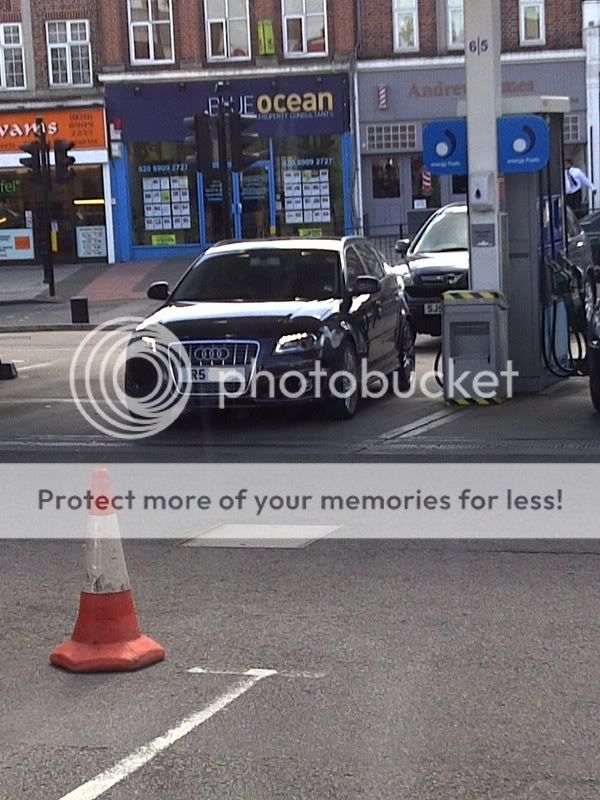
At last!!! DRL's baby!!!
 Not the best of pics but as you can see they are all working without any errors...
Now I gotta work out just what I did when upgrading my central electrics module to the newer version that stopped my washer jets from working
Seems on this occasion I was over thinking things... Kufatec's loom was spot on in the beginning tbf to em, but I have read on many occasions that there looms leave a lot to be desired... Now I am slightly more well versed with the wiring side of thing of things I will be looking into making up looms for any future retrofits.
So I got the correct repair wires to replace the connectors I had chopped off the kufatec loom, removed my main/ high beam wires out of Plug A pin 3 and Plug D pin 3 stuck the repaired kufatec loom wiring back into these pins, a bit of coding and here's the end result....
At last!!! DRL's baby!!!
Not the best of pics but as you can see they are all working without any errors...Now I gotta work out just what I did when upgrading my central electrics module to the newer version that stopped my washer jets from working
Khufu
Registered User
Glad to hear you got there in the end! What repair wire did you end up using?
I see you have got washers sorted to
I see you have got washers sorted to
Lings
Registered User
The Only thing is .....I think there not as bright as the one's on the 2010 plate Audi a3's .........Does anybody know how to make them brighter ? I just saw one like 10 min ago and there not as bright as RS's....
Will sort better pics once I get it lowered steve 
Digzz man.... don't put a downer on it lemme enjoy them for today at least! haha!!
Hi Khufu it was the 2.5mm one can't remember what the part no. ended with now. But when you look in additional notes for relevant Plug as you did in this thread it will be the 2.5mm one.
Digzz man.... don't put a downer on it lemme enjoy them for today at least!
haha!!Hi Khufu it was the 2.5mm one can't remember what the part no. ended with now. But when you look in additional notes for relevant Plug as you did in this thread it will be the 2.5mm one.
Last edited:
Will sort better pics once I get it lowered steve
Digzz man.... don't put a downer on it lemme enjoy them for today at least!
I'm sorry ....But I'm a OEM Boffin .
 Can't help it.....lol
Anyway, I just seen one and mine looked just as bright!
We need to compare side by side.....lol ....Real talk !!!!!
Anybody in The North West area of London that owns a 2009-2010-2011 plate ......PM Me or RS....To compare...L.E.D'S ..Please.... Quick tings...lol


