

jimbobery
S3
- Joined
- May 6, 2008
- Messages
- 257
- Reaction score
- 0
- Points
- 16
Ive been suffering the common xenon light problem where they randomly point to the ground. Ive read on here that the solution is a new levelling motor unit, but its always bothered me that the motors physically work and adjust the light level, its just they go mad sometimes and point to the ground. So, being a big fan of fixing stuff myself instead of paying out money I decided to take the motor apart to see if I can fix it, and it seems to have worked as the light has stayed at the right level for a few journeys now. I took some pics along the way so thought Id share my experience and hopefully it will work for others.
Obviously Im not 100% sure that the motor is fixed as it was an intermittent fault but it happened more often than not, and hasnt happened since Ive messed around with it. This doesnt mean this process will work for anyone else, and you follow this guide at your own risk. Also bear in mind Ive no idea what Im doing, I just figured I might as well take the motor apart and try and fix it before buying a new one I cant make it any worse!
Removing the motor is fairly easy but can be fiddly. My lights are facelift but the process should be the same for pre-facelift lights except that the motor is on the other side of the light unit. I worked on the drivers side motor but I guess its the same for the other side. The motor goes into the light from the back of the light unit towards the front of the car. Firstly remove the plug connector to the motor. Twisting the motor towards the centre of the car about a quarter turn releases the motor, but it is still connected to the internal light. The motor unit ends in a ball which slots into a horizontal bar inside the light. To remove the ball from the bar you have to twist the motor unit to slide the ball off the end of the bar. This pic shows the bar you have to slide out of. Ive shamelessly nicked this pic off one of jonS3s posts.

The back cover of the motor is removed by prising the clips open:

Inside you can remove the PCB by removing the two rubber grommet things and pulling the PCB out. The motor comes out with the PCB:

The motor now slides off the PCB. On the back of the PCB is some sort of slider that reads the position of the light. I thought it best to clean this part by gently prising open the little metal flaps, bending the bottom flap and then gently bending the grey part of the part to open it up:

You can then remove the grey slider bar. Note the fitting of this bar so that you put it back the same way:
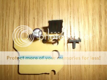
Next I cleaned the insider of the slider, the slider its self, and the main PCB with electrical contact cleaner. I then gently bent the wire prongs on the slider bar out so that when refitted it would exert more pressure and hopefully improve the electrical contact.
Next I refitted the slider bar and closed up the part by bending the little metal bits back into place. Make sure the slider bar is back in the correct way round and that it slides freely up and down. If it doesnt then loosen the little metal clips.

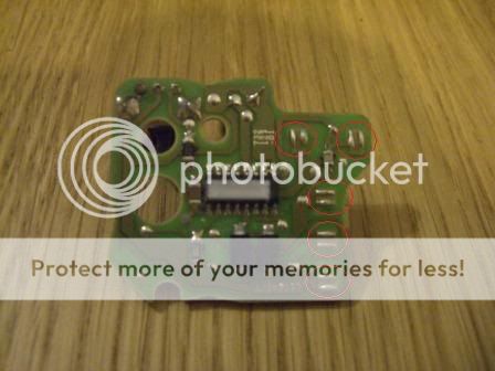
Next I inspected the front of the PCB for any loose soldering. I didnt really find any, but if you do then solder the joint again.
I did decide to try and improve the contact points on the PCB by resoldering them. I simply added a bit more solder to bulk them out as the seemed a bit worn out.
Before:

After:
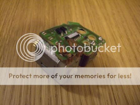
Next I bent in the connectors on the motor and bent out the connectors on the covering case to improve their contact pressure on the PCB:


Clip the motor back onto the PCB:
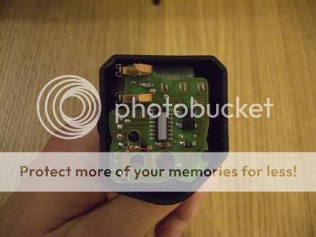
Before putting the motor and PCB back into the housing note that the grey slider bar on the PCB fits into the slot in the white part of the housing:

Put the motor and PCB back into the housing. Once in the housing, refit the rubber grommets. Then use a small screwdriver to push the grey slider bar into its housing by using the hole in the PCB. The bar clicks into place:
Now refit the cover and refit the motor to the light. This is reversal of removal. Firstly get the ball at the end of the motor into the horizontal bar inside the light. This is made easier by removing the back cover from the light and pulling the inside of the light towards the motor to bring the horizontal bar closer. Again slide the ball into the bar by twisting the motor, then refit the motor and refit the plug connector to the motor.
Obviously Im not 100% sure that the motor is fixed as it was an intermittent fault but it happened more often than not, and hasnt happened since Ive messed around with it. This doesnt mean this process will work for anyone else, and you follow this guide at your own risk. Also bear in mind Ive no idea what Im doing, I just figured I might as well take the motor apart and try and fix it before buying a new one I cant make it any worse!
Removing the motor is fairly easy but can be fiddly. My lights are facelift but the process should be the same for pre-facelift lights except that the motor is on the other side of the light unit. I worked on the drivers side motor but I guess its the same for the other side. The motor goes into the light from the back of the light unit towards the front of the car. Firstly remove the plug connector to the motor. Twisting the motor towards the centre of the car about a quarter turn releases the motor, but it is still connected to the internal light. The motor unit ends in a ball which slots into a horizontal bar inside the light. To remove the ball from the bar you have to twist the motor unit to slide the ball off the end of the bar. This pic shows the bar you have to slide out of. Ive shamelessly nicked this pic off one of jonS3s posts.
The back cover of the motor is removed by prising the clips open:
Inside you can remove the PCB by removing the two rubber grommet things and pulling the PCB out. The motor comes out with the PCB:
The motor now slides off the PCB. On the back of the PCB is some sort of slider that reads the position of the light. I thought it best to clean this part by gently prising open the little metal flaps, bending the bottom flap and then gently bending the grey part of the part to open it up:
You can then remove the grey slider bar. Note the fitting of this bar so that you put it back the same way:
Next I cleaned the insider of the slider, the slider its self, and the main PCB with electrical contact cleaner. I then gently bent the wire prongs on the slider bar out so that when refitted it would exert more pressure and hopefully improve the electrical contact.
Next I refitted the slider bar and closed up the part by bending the little metal bits back into place. Make sure the slider bar is back in the correct way round and that it slides freely up and down. If it doesnt then loosen the little metal clips.
Next I inspected the front of the PCB for any loose soldering. I didnt really find any, but if you do then solder the joint again.
I did decide to try and improve the contact points on the PCB by resoldering them. I simply added a bit more solder to bulk them out as the seemed a bit worn out.
Before:
After:
Next I bent in the connectors on the motor and bent out the connectors on the covering case to improve their contact pressure on the PCB:
Clip the motor back onto the PCB:
Before putting the motor and PCB back into the housing note that the grey slider bar on the PCB fits into the slot in the white part of the housing:
Put the motor and PCB back into the housing. Once in the housing, refit the rubber grommets. Then use a small screwdriver to push the grey slider bar into its housing by using the hole in the PCB. The bar clicks into place:
Now refit the cover and refit the motor to the light. This is reversal of removal. Firstly get the ball at the end of the motor into the horizontal bar inside the light. This is made easier by removing the back cover from the light and pulling the inside of the light towards the motor to bring the horizontal bar closer. Again slide the ball into the bar by twisting the motor, then refit the motor and refit the plug connector to the motor.
