I bought my loom from Kufatec to fit S3 Recaros in my A3 8L. Not sure if this any use but here are the instructions they provided me with (Google translated from German)....will see if I have any other documentation if you think it will help.
Installation instructions harness for heated seats
All works on the central electrical disconnect the battery!
Wiring instructions:
The two larger plugs next to each other on the two switches on the center console.
The "F" stands for driver's side, the "B" for passenger side. Then on to the left
Fuse carrier. The cable on the driver side up along with the driver's seat (shorter
End). Come from the center tunnel to the front passenger seat () longer end.
Connection:
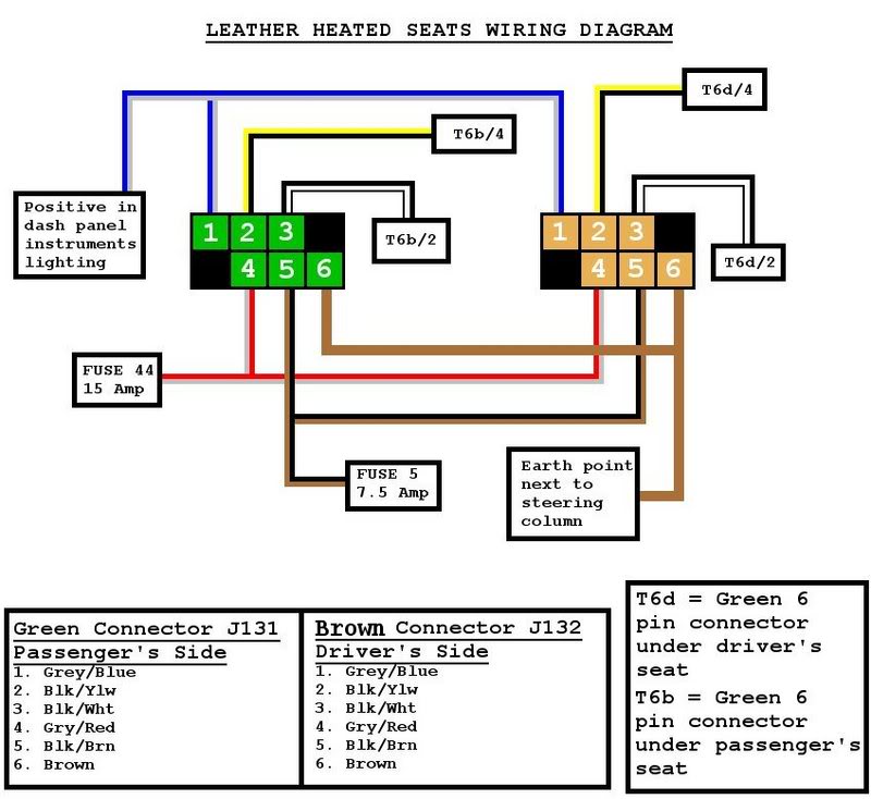
The gray line is connected to pin 5 of the 6-way connector on the controller for lighting
Switches and instruments. If this pin is not used for this release included the current terminal.
This line is responsible for the illumination of the switch (Kl.58b). Close Next
Plus we are the connection (terminal 15 ignition) at. The fuse for this is S 5 and A with 7.5
hedged. The 7.5 A fuse is part number N 102 615 02 For this purpose you have to the
Unscrew the fuse holder and insert the black wire in the fuse holder.
To insert the contact-violent can you have the pink additional locking approximately 2 mm
button to the right!
Image 1
http://i.imgur.com/yXy5hDl.jpg
The red line (KL 30 permanent) is the same way in the fuse carrier. The
Assurance of this is the S 44 and is secured with 15 A. The 15A fuse has
Part number N 017 131 12th Here you have the additional locking pink about 5 mm down
. Press Then you put on the red line from the harness in place of the white and red line
the picture. The single red line you put in the second slot of this assurance (on the
Image is also a red line). The other end of this cable has a 6mm her lug the
to the screw at the bottom of the relay carrier attached labeled terminal 30.
Image 2
http://i.imgur.com/12F7F1P.jpg
The brown line you screwed firmly to the ground point next to the docking station on the A-pillar ..
Under your seats the whole thing would look like this.
Image 3
http://i.imgur.com/QnBHno0.jpg
Here you will put the two black 6-pin connector in each of the driver or
Passenger seat.
Now a few part numbers for spare part search:
1J0 963 555 B seat heater
1J0 963 557 C backrest heater
1J0 963 563 B 01C switch / control unit heated seats
---
Instruction for additional wiring harness mirror memory
10-pin connector brown below the driver's seat
Pin 2 - yellow
Pin 3 - white
Pin 4 - Red
Pin 5 - Brown
Pin 6 - Green
Pin 7 - purple
Pin 8 - Blue / Red
Blue 10-pin connector A-pillar on the left (driver's side)
Pin 3 - Red
Pin 7 - purple
Pin 9 - green
Pin 10 - Brown
Blue 10-pin connector A-pillar on the right (passenger side)
Pin 3 - Red
Pin 7 - White
Pin 9 - yellow
Pin 10 - Brown
------
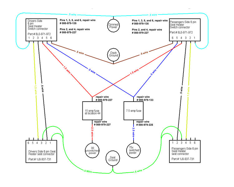
Wiring instructions for wiring harness seats + seat adjustment with memory
Function driver side Golf 4
thin black line - Fuse S5 (terminal 15) with easy to clamp means
Current terminal to the black / blue wire off
red / yellow wire - Fuse S44 (terminal 30), both red lines in these
Backup slot
Ring terminal to screw terminal 30 Micro Central Electric,
30 A fuse
black line - Fuse S1 (Kl.75x) to the red / brown wire me off
gray line - light switch (Kl.58b) using current terminal to pin 17
Light switch connector (gr / bl)
Brown wire - Ground beneath the steering column
gray line with white spout - diagnostic connector pin 7 here should soldered best
be because 0.35 sqmm
Yellow / Green line - canbus low, pin 6 (or / br) connector on 23polig
Comfort system control unit solder because 0.35 sqmm
yellow line - canbus high, pin 9 (or / gn) plug 23polig
Comfort system control unit solder because 0.35 sqmm
-----------------


")